OperationInstruction_Vsision XP.pdf - 第194页
Page 186 V ISION XP+ V AC 7 Alarm Messages 7.17 Minimum T emperature T o lerance Fallen Short Off Operating Instructions V ersion 1.5 7.17 Minimum T empe rature T o lerance F allen S hort Off One or more actual temperatu…
VISION XP+ VAC Page 185
7 Alarm Messages
7.15 Speed (option)
Operating Instructions
Version 1.5
7.15 Speed (option)
7.16 Standstill Monitoring (option)
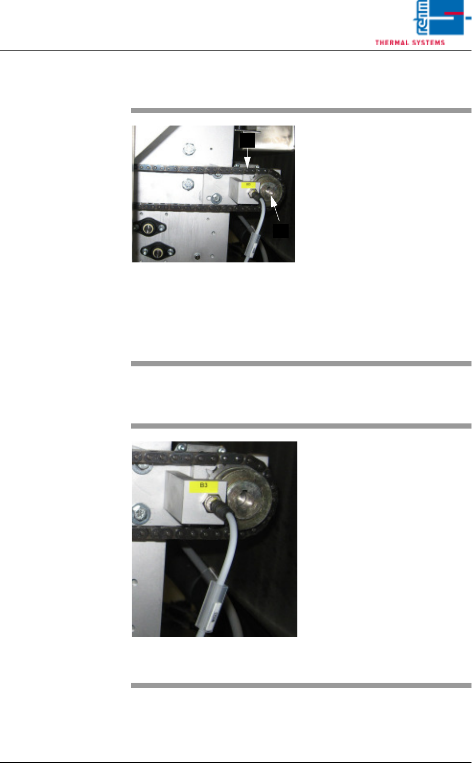
Fig. 7-15 Conveyor Chain
The conveyor chain is too slow or
too fast relative to the selected
Rel+/- values.
Possible causes:
• The conveyor has been overload-
ed.
• Conveyor chain lubrication has
failed.
• The drive motor (A) is defective.
• The slip clutch (B) is loose.
• The conveyor impulse is not right.
Caution!
The work steps to be completed in-
volve danger of pinching.
B
A
Fig. 7-16 Band pulse sensor
The transport chain doesn't move,
although the drive motor is running.
The friction clutch rotates freely.
Procedure:
• Check to see whether or not the
conveyor chain is running. Re-
move any jammed parts.
• Check the slip clutch for correct
adjustment.
• Check the chain sprocket sensor
for correct functioning.
• Inspect the drive motor.
Caution!
The work steps to be completed in-
volve danger of pinching.

Page 186 VISION XP+ VAC
7 Alarm Messages
7.17 Minimum Temperature Tolerance Fallen Short
Off
Operating Instructions
Version 1.5
7.17 Minimum Temperature Tolerance Fallen Short Off
One or more actual temperature values have fallen below the Rel- tolerance
limit.
Possible causes:
• Too little heating power (Y max.) has been selected at the heater settings.
• The heater controller is defective, or has failed.
• The system is in the warm-up phase.
Procedure:
• Determine whether or not available heating power is adequate.
• The modul thermocouple is not plugged in correctly, or has failed.
7.18 Maximum Temperature Limit Value Exceeded
One or more actual temperature values have exceeded the specified tem-
perature limit MAX.
Possible causes:
• A temperature sensor is defective.
• Temperature setpoints have been set too high (close to or greater than the
upper limit value). A difference of at least 10 Kelvin is required.
• The modul thermocouple is not plugged in correctly, or has failed.
Procedure:
• Inspect the temperature sensor.
• Check the temperature setpoints.
• Determine whether or not such a high temperature is necessary. If so, de-
termine whether or not the upper limit value can be adjusted.
• Check the temperature controller settings.
• The coolant water flow rate is inadequate.
7.19 Maximum Temperature Tolerance Exceeded
One or more actual temperature values have exceeded the specified Rel+
tolerance limit.
Possible causes:
• The physical limits of the heating zones have been exceeded.
• The coolant water flow rate is inadequate.
Procedure:
• Check the selected temperature profile.
VISION XP+ VAC Page 187
7 Alarm Messages
7.20 Heating Element Monitoring, Power Controller
Operating Instructions
Version 1.5
• Check the temperature controller settings.
7.20 Heating Element Monitoring, Power Controller
7.21 PCB Feed Monitoring (option)
The PCBs have not arrived at the outlet within the specified period of time.
Possible causes:
• PCBs have jammed within the system.
• Operator’s hands are in the inlet area.
• The sensor at the inlet has been obstructed more than once.
• The sensor at the outlet has not detected the PCB.
• One of the sensors is defective.
7.22 PCB Transfer
Possible causes:
• The sensor at the outlet is obstructed too long, or continuously.
• The sensor is incorrectly adjusted or bent.
• The PCBs are becoming jammed. An error has occurred at the next down-
stream device.
Procedure:
Click the Reset PCBs button and acknowledge the error.
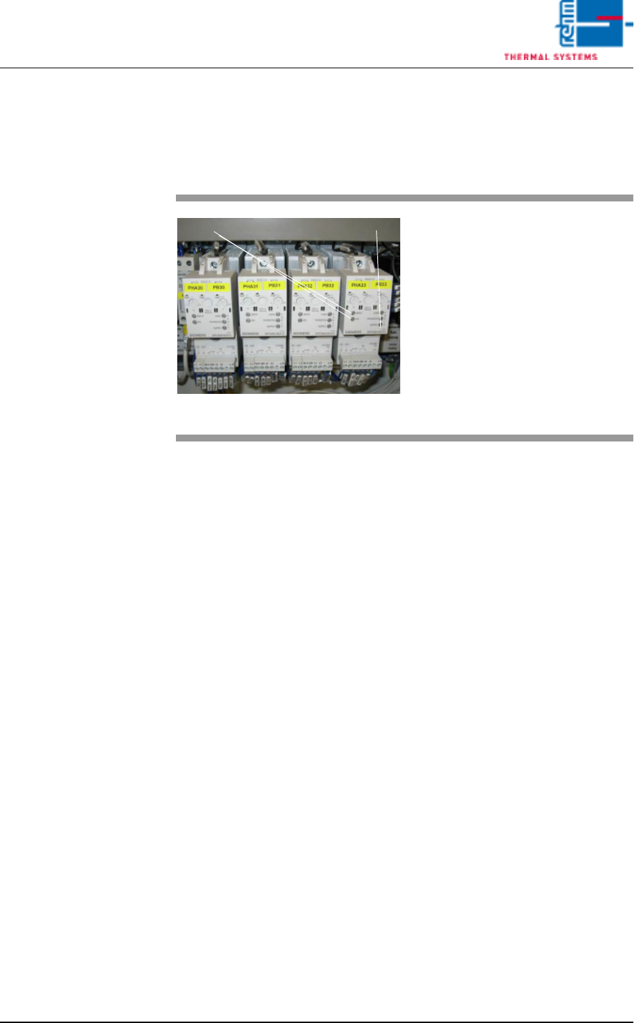
Fig. 7-17 Power Controller
Too little or no current at all is avail-
able to the pyrolysis system.
Possible causes:
• If the fuse has blown, perform ap-
propriate measurement of the
heater and replace if necessary.
• Fuse has not blown, e.g. in the
event of extreme mains fluctua-
tion. The power controller must be
recalibrated.
INPUT ON
Error display