OperationInstruction_Vsision XP.pdf - 第45页
Vision XP+ V AC Page 37 3 From Tr ansport to Initial Start-Up 3.3 Connections Operating Instructions V ersion 1.5 3.3.4 Water , Pressure air and Nitrogen Connections (option) Fig. 3-1 2 VX P connecti ons coolin g water e…
Page 36 Vision XP+ VAC
3 From Transport to Initial Start-Up
3.3 Connections
Operating Instructions
Version 1.5
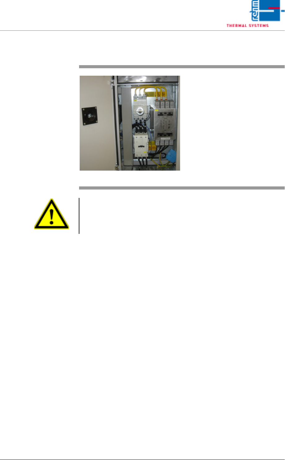
3.3.3 Electrical Connection
Fig. 3-11 Electrical Connection
Refer to the circuit diagrams for con-
nected loads. The mains connection
must be accordingly fused.
The connected line will be connect-
ed directly to the line filter.
Warning!
The system is operated with mains power. System components conduct life
endangering voltages, even when the mains switch is turned off. Improper
handling of the system may result in death or severe personal injury, as well
as substantial property damage.

Vision XP+ VAC Page 37
3 From Transport to Initial Start-Up
3.3 Connections
Operating Instructions
Version 1.5
3.3.4 Water, Pressure air and Nitrogen Connections (option)
Fig. 3-12 VXP connections cooling water ex-
ternal cooling, nitrogen and com-
pressed air
Refer to the circuit diagram or the
technical data sheet for connected
loads.
Caution!
Unless absolutely necessary, do not
disconnect the nitrogen or the cool-
ant water lines when pressurized:
Danger of injury!

Page 38 Vision XP+ VAC
3 From Transport to Initial Start-Up
3.4 Initial Start-Up
Operating Instructions
Version 1.5
3.4 Initial Start-Up
3.4.1 Preparation
Please check the following points before configuring the system:
1. The system has been set up in accordance with the setup instructions.
2. Electrical supply power is in compliance with the specifications included
in the operating instructions and the “Technical Data Sheet”.
3. Make sure that the system has been connected to electrical power, com-
pressed air, nitrogen and coolant water.
4. Make sure that the system has been connected to the exhaust air sys-
tem.
5. Make sure that all required fluids (coolant water, chain oil) have been
filled up.
6. Conduct a visual inspection of the system. It is especially important to
ensure that there are no obstacles within the conveyor system’s travel
path.
7. All process chambers and hoods must be closed.
8. Make sure that all emergency-stop buttons are deactivated.