OperationInstruction_Vsision XP.pdf - 第40页
Page 32 Vision XP+ V AC 3 From T ransport to Initial Start-Up 3.1 T ransport Configuration and T ransport Operating Instructions V ersion 1.5 3.1.4 T ransport in the W ooden Crate Dimensions Fig. 3-5 Dimension s with Woo…
Vision XP+ VAC Page 31
3 From Transport to Initial Start-Up
3.1 Transport Configuration and Transport
Operating Instructions
Version 1.5
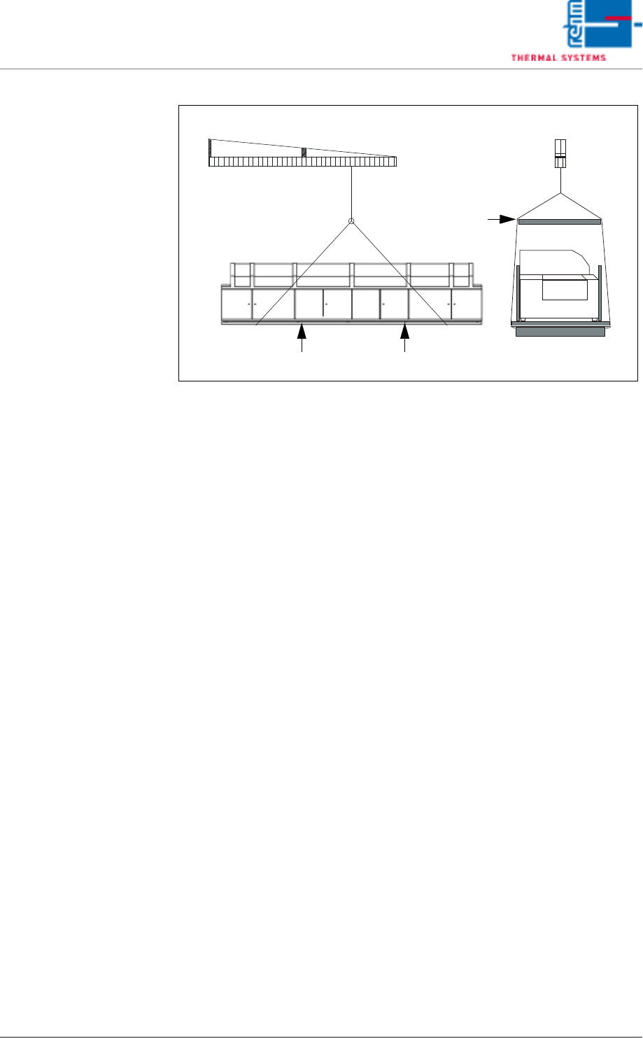
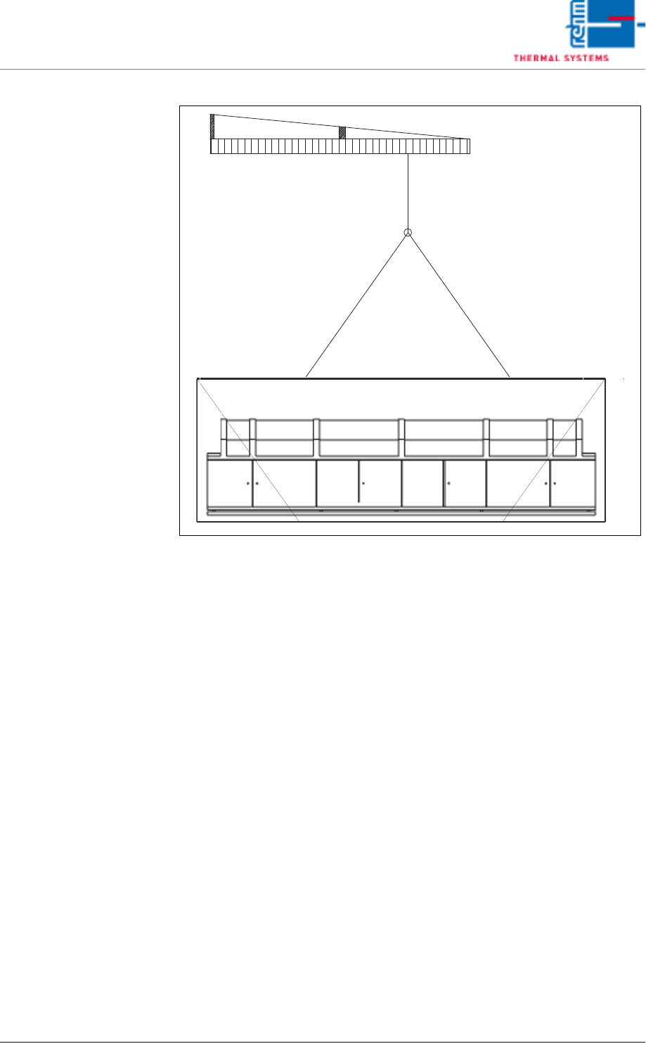
Transport with Crane
Fig. 3-4 Transport with Crane
Girder
Padded Side Panels
Page 32 Vision XP+ VAC
3 From Transport to Initial Start-Up
3.1 Transport Configuration and Transport
Operating Instructions
Version 1.5
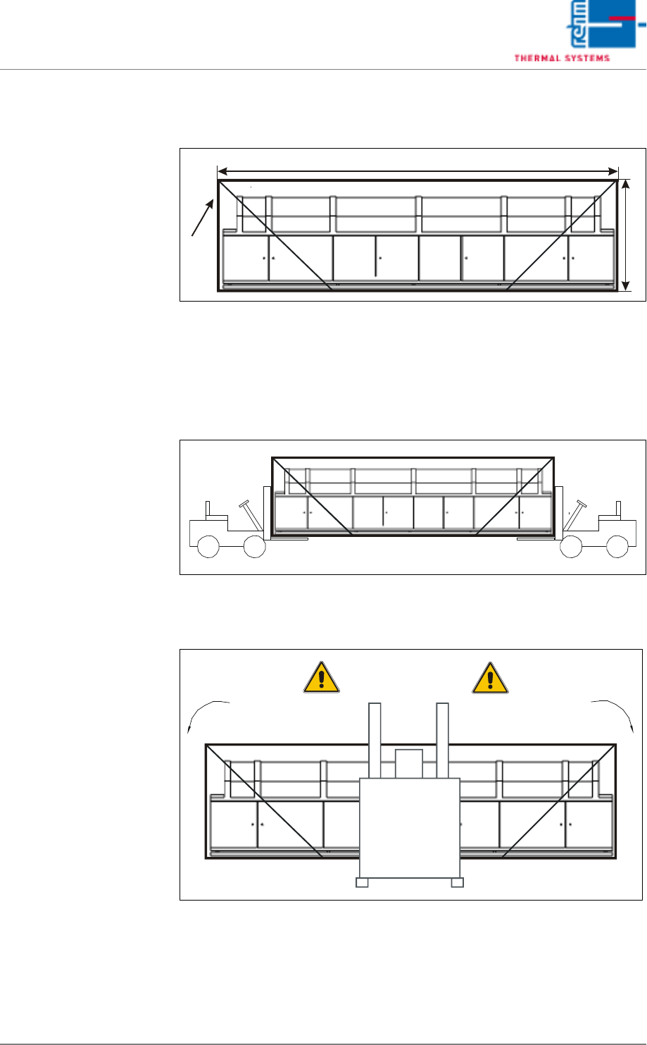
3.1.4 Transport in the Wooden Crate
Dimensions
Fig. 3-5 Dimensions with Wooden Crate
Length (A), width (B) and height (C) are specified in the installation plan. Ap-
proximately 400 mm must be added to the dimensions specified in the instal-
lation plan.
Transport in Wooden
Crate with Two Forklifts
or Pallet Jacks
Fig. 3-6 Transport in Wooden Crate with Two Forklifts or Pallet Jacks
Transport in Wooden
Crate with One Forklift
or Pallet Jack
Fig. 3-7 Transport in Wooden Crate with Forklift or Pallet Jack
A
C
B
Danger of Tilting
Vision XP+ VAC Page 33
3 From Transport to Initial Start-Up
3.2 Setup Instructions
Operating Instructions
Version 1.5
Transport in Wooden
Crate with Crane
Fig. 3-8 Transport in Wooden Crate with Crane
3.2 Setup Instructions
The installation place has to be dust-free and dry. The permissible ambient
temperature is +5°C until +35°C.
1. Turn all inside leveling feet in until the system is supported exclusively
by the four leveling feet at the corners.
2. Adjust the leveling feet such that the conveyor is at the same height as
the conveyor system of the upstream machine.
3. Make sure that the distance from the system inlet and the system outlet
to adjacent equipment is at least 1 cm.
4. Precisely level the system, both widthwise and lengthwise, with the help
of a level.
5. Turn the inside leveling feet out until the machine base no longer sags
(visual inspection).
6. Secure the leveling feet with lock nuts.
7. Install the components which have been removed for transport.
8. Connect all supply lines.