OperationInstruction_Vsision XP.pdf - 第72页
Page 64 Vision XP+ V AC 4 Equipment 4.4 The Process Chamber Operating Instructions V ersion 1.5 4.4.14 Nitrogen Lock at the Outlet 4.4.15 O utlet Area Fig. 4-4 0 Nitrog en Lock a t the Out let Nitrogen lock separates the…
Vision XP+ VAC Page 63
4 Equipment
4.4 The Process Chamber
Operating Instructions
Version 1.5
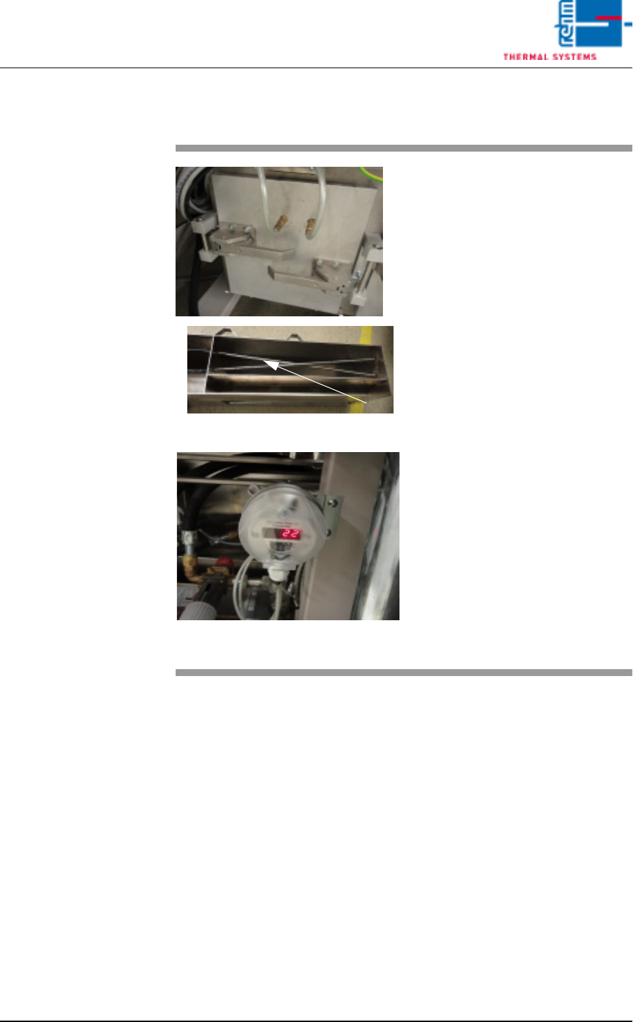
4.4.13 Volume flow control, cooling section (option)
Fig. 4-38 Volume flow measurement
Fig. 4-39 Differential pressure gauge for cvo-
lume flow measurement
The volume flow through the cooling
section is measured via dynamic
pressure drop.
Two dynamic pressure sensors are
to this end integrated at a defined
point in the air duct – as shown on
the right.
The first dynamic pressure sensor
records the total flow pressure.
The second dynamic pressure sen-
sor records the static pressure.
The differential pressure gauge indi-
cates the difference between these
two values.
The volume flow is calculated inter-
nally based on the known cross-
section and the gas temperature.
The actual volume flow is main-
tained by activating the volume flow
control function via the visualisation.
Page 64 Vision XP+ VAC
4 Equipment
4.4 The Process Chamber
Operating Instructions
Version 1.5
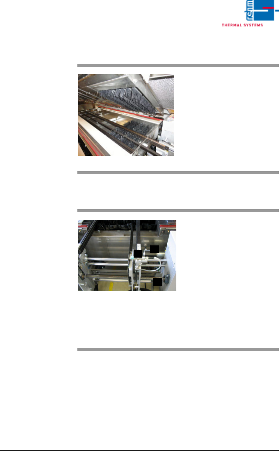
4.4.14 Nitrogen Lock at the Outlet
4.4.15 Outlet Area
Fig. 4-40 Nitrogen Lock at the Outlet
Nitrogen lock separates the cooling
section from outlet area.
It is comprised of flow barriers, and
it improves the oxygen-free state of
the air.
Fig. 4-41 Outlet Area with ultrasonic sensor
The outlet area includes:
A) The sensor for the interfaces and
for counting all PCBs which have
been soldered since the system
was switched on.
B) The drive motor with slip clutch
for the PCB conveyor
C) The adjusting mechanism for the
conveyor system
D) The pulse sensor (located at the
rear of the system)
Escaping soldering vapors are
drawn off into a removable metallic
gauze filter located in the cover.
C
B
A
Vision XP+ VAC Page 65
4 Equipment
4.4 The Process Chamber
Operating Instructions
Version 1.5
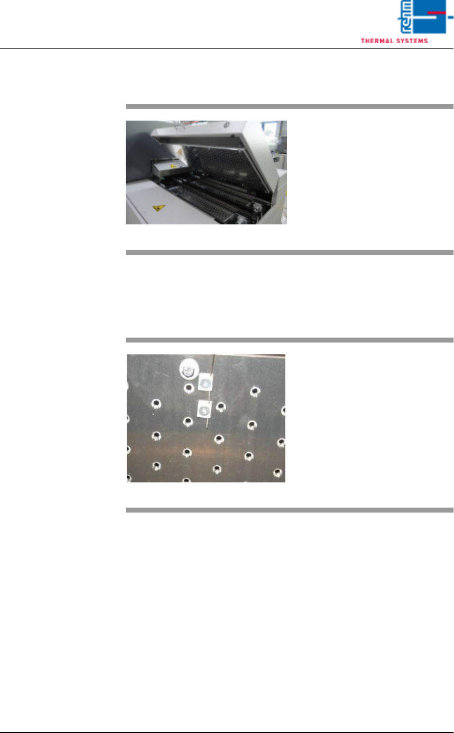
4.4.16 Active cooling module (option)
4.4.17 Internal Temperature Monitoring (option)
Fig. 4-42 Active cooling module
An active cooling module can also
be fitted at the outlet of the system
to enable additional cooling of sub-
assemblies.
Fig. 4-43 Internal Temperature Sensor
Temperature is monitored in the in-
dividual heat zones by means of
sensors which are located directly at
the conveyor level. A sensor for
measurement of the interior temper-
ature is connected at each nozzle
field.
Tolerances and limit values which
are intended to trigger an alarm can
be selected as desired by the user.