OperationInstruction_Vsision XP.pdf - 第74页
Page 66 Vision XP+ V AC 4 Equipment 4.4 The Process Chamber Operating Instructions V ersion 1.5 4.4.18 P rocess Chamber Elevator Fig. 4-4 4 Proces s Chambe r Eleva tor A motor drives th e spindles, which in turn lift the…
Vision XP+ VAC Page 65
4 Equipment
4.4 The Process Chamber
Operating Instructions
Version 1.5
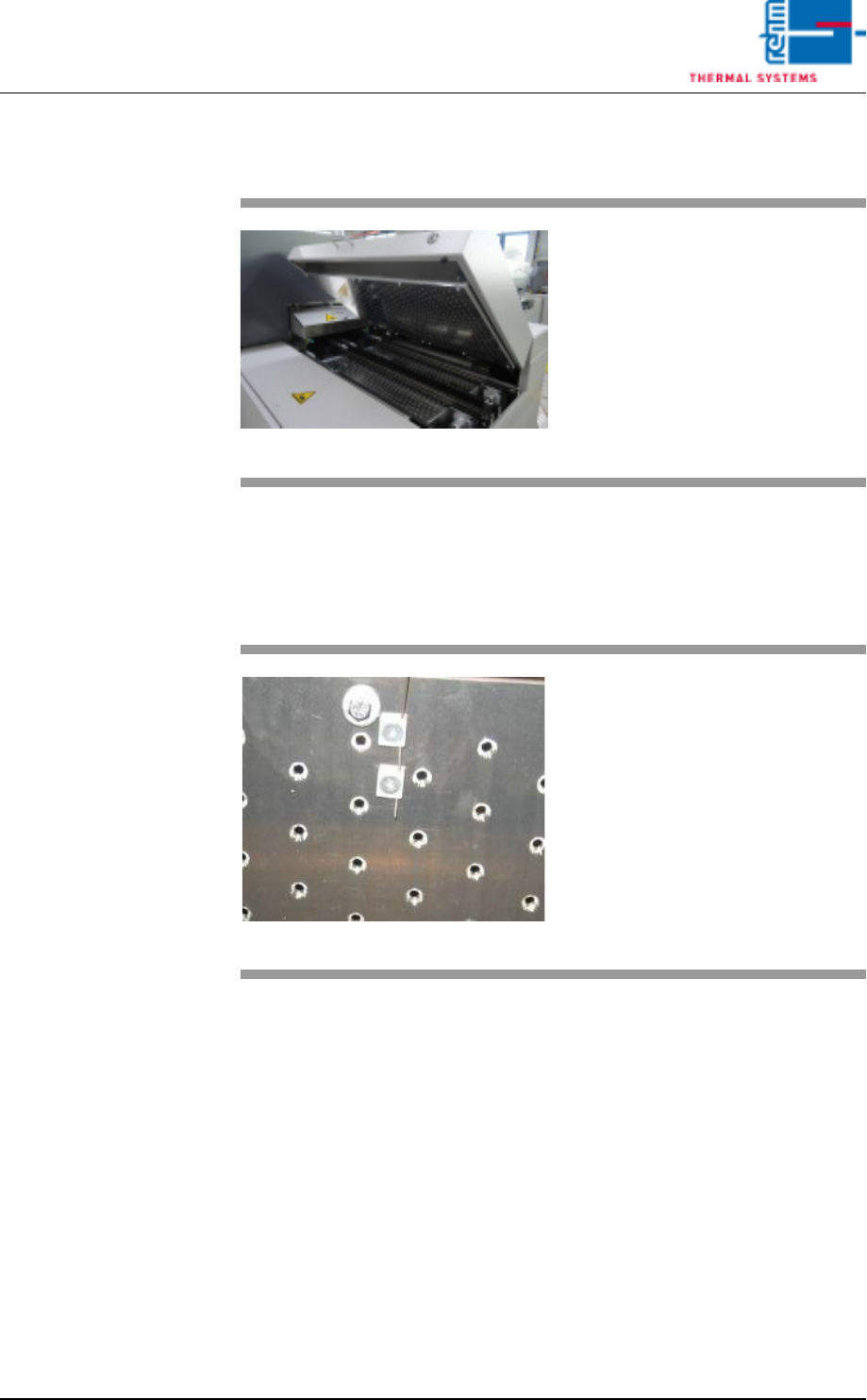
4.4.16 Active cooling module (option)
4.4.17 Internal Temperature Monitoring (option)
Fig. 4-42 Active cooling module
An active cooling module can also
be fitted at the outlet of the system
to enable additional cooling of sub-
assemblies.
Fig. 4-43 Internal Temperature Sensor
Temperature is monitored in the in-
dividual heat zones by means of
sensors which are located directly at
the conveyor level. A sensor for
measurement of the interior temper-
ature is connected at each nozzle
field.
Tolerances and limit values which
are intended to trigger an alarm can
be selected as desired by the user.

Page 66 Vision XP+ VAC
4 Equipment
4.4 The Process Chamber
Operating Instructions
Version 1.5
4.4.18 Process Chamber Elevator
Fig. 4-44 Process Chamber Elevator
A motor drives the spindles, which
in turn lift the process chamber.
Positioning of the process cham-
bers is initialized by buttons on the
main screen.
See also chapter Software,
Fig. 5-11 Main Window, on page 85.
Vision XP+ VAC Page 67
4 Equipment
4.5 Pyrolysis System
Operating Instructions
Version 1.5
4.5 Pyrolysis System
Process gas which is contaminated during soldering is purified in the pyrol-
ysis unit and returned to the soldering process.
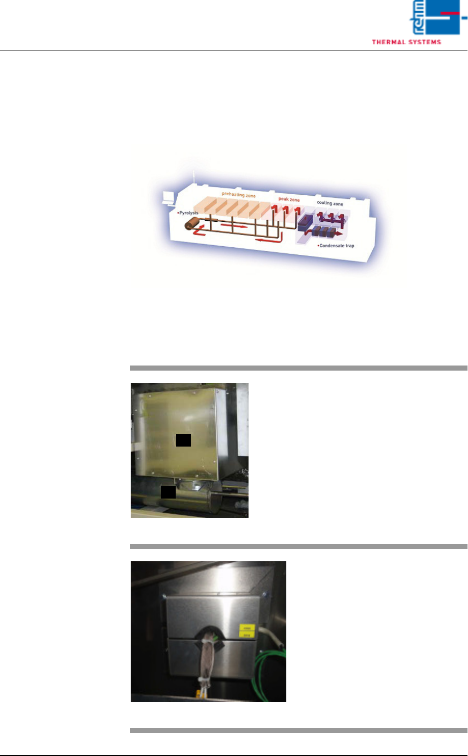
Fig. 4-45 Gas Flow in the Pyrolysis System
Contaminated gas is exhausted from preheating right on up to the peak
zone. The gas is then purified by means of pyrolysis and is blown back into
the peak zone.
Fig. 4-46 Pyrolysis System
A)Pyrolysis box
B)Venturi tube
The Venturi tube propels gas
through the pyrolysis system.
Throughput is measured by means
of the flow meter. The flow meter is
located on the adjusting panel for
nitrogen distribution (see Fig. 4-54).
Fig. 4-47 Pyrolysis Connections
• 3 heater connections
• 1 pc. connection for gas tempera-
ture Pyrolysis.
• 3 pc. temperature sensors
B
A