OperationInstruction_Vsision XP.pdf - 第58页
Page 50 Vision XP+ V AC 4 Equipment 4.3 Conveyor System Operating Instructions V ersion 1.5 4.3.2 Bushing Chain Conveyor PCBs are advanced through the s ystem by two ch ains wh ich are g uided v ia aluminum prof iles. Th…
Vision XP+ VAC Page 49
4 Equipment
4.3 Conveyor System
Operating Instructions
Version 1.5
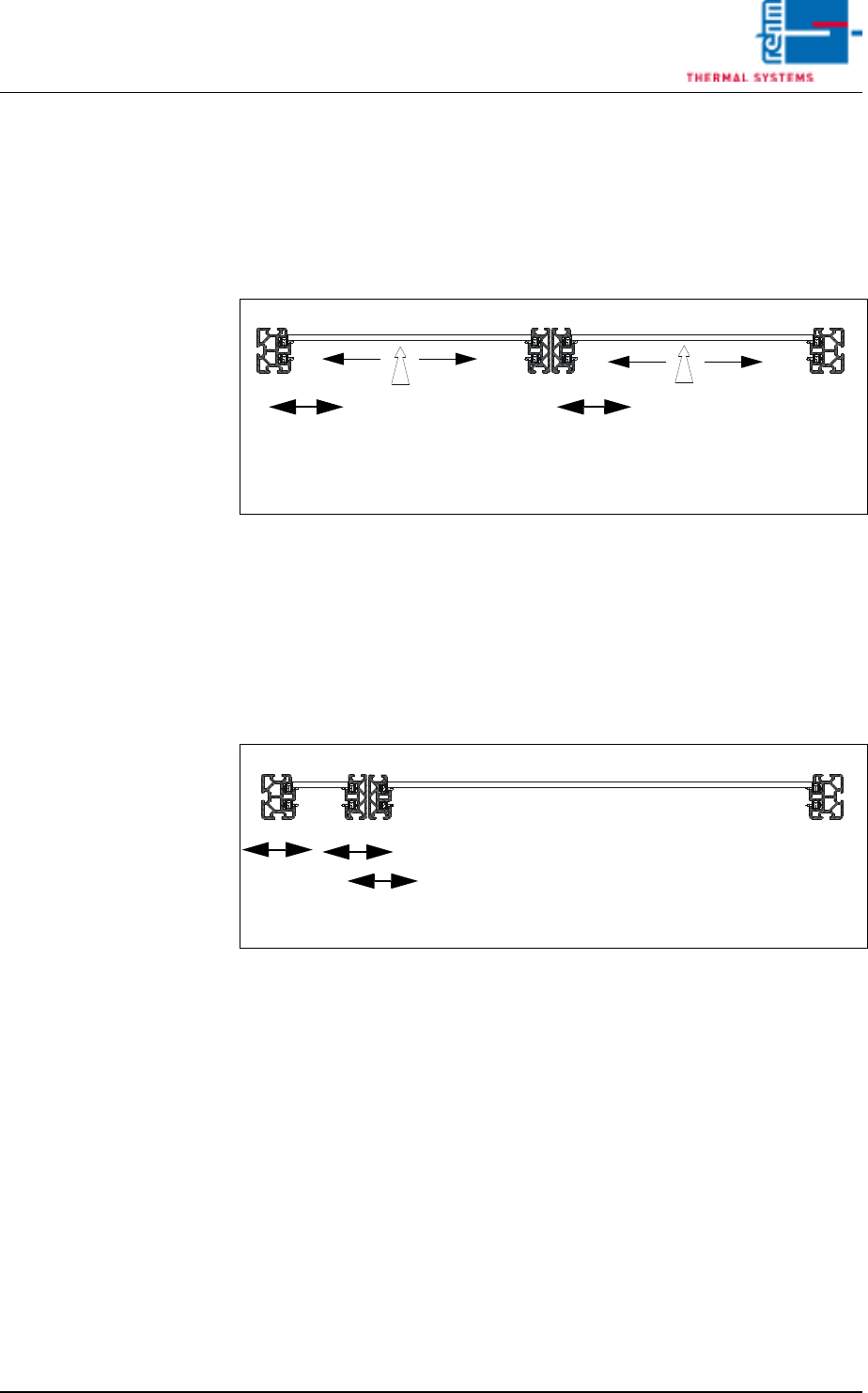
Dual-lane conveyor This option makes it possible to advance two PCBs through the system at
the same time. The first and third conveyor side panels are permanently
mounted, and the fourth is moved synchronously along with the second dur-
ing width adjustment. A center support can be optionally installed for each
lane. The speed of both lines can be determined either synchronous by one
drive motor or asynchronous by two drive motors.
Dual-lane multitrack
conveyor
PCBs with different widths can be advanced through the system with the
multitrack conveyor. The first conveyor side panel on the operator side is
permanently mounted. The other conveyor side panels can be separately
adjusted without restriction with their own drive motors. The speed of both
lines can be determined either synchronous by one drive motor or asynchro-
nous by two drive motors.
Fixed Side
Operating Side
1
2
34
Adjustable Side
CS
CS
Fixed Side
Adjustable Side
Panel
Panel
Panel
Panel
Fixed Side
Operating Side
1
2
34
Adjustable Side Panels
Panel
Page 50 Vision XP+ VAC
4 Equipment
4.3 Conveyor System
Operating Instructions
Version 1.5
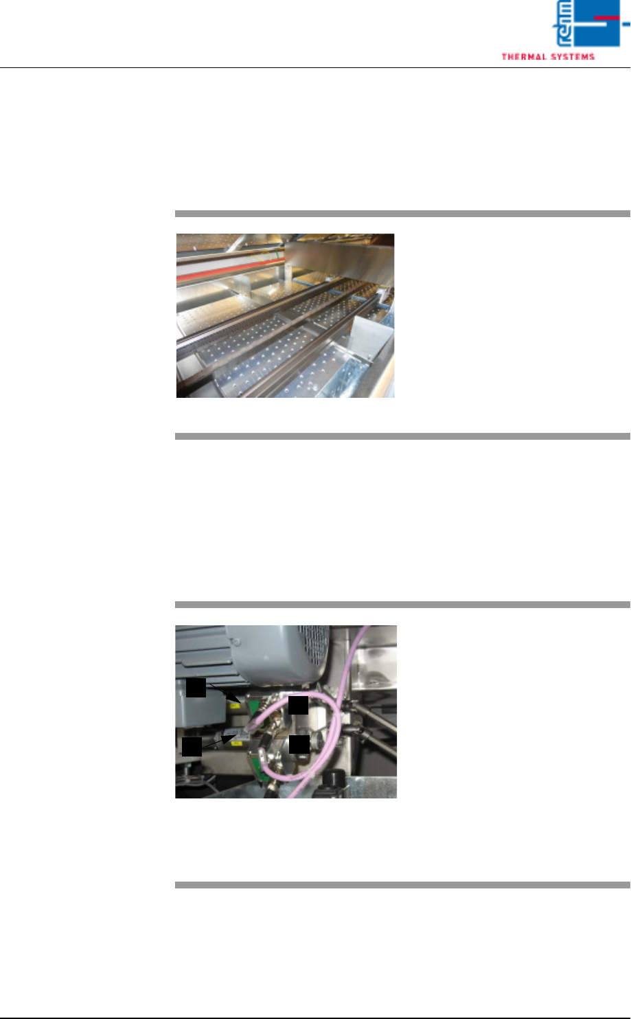
4.3.2 Bushing Chain Conveyor
PCBs are advanced through the system by two chains which are guided via
aluminum profiles. The PCBs lie on top of the extended link pins of these
chains.
4.3.3 Drive / Width adjustment
The drive unit consists of a brushless motor with integrated speed control
electronics. A slip clutch disengages the motor from the chain conveyor. This
becomes necessary if the specified torque value is exceeded (e.g. if the
chain drive is blocked by a PCB).
Standard: fixed rail right hand (passage direction).
Adjustable side panels are driven by means of DC motors. Position is ascer-
tained by means of an absolute rotary encoder.
Fig. 4-10 Bushing Chain Conveyor
Pin chain is located in the side
plates of the process chamber.
Indication: Longitudinal thermal
chain expansion is compensated by
means of spring tensioners.
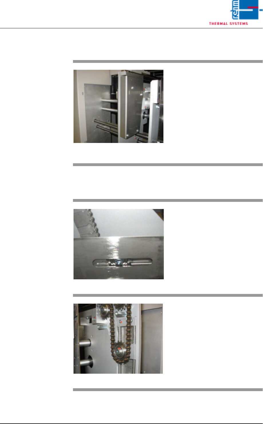
Fig. 4-11 Motor with Shaft
Motor and through shafts for the
width adjustment of Center Board
Support and PCB´s are located at
the front side of the system, under
the rear area of the cooling section.
A) Motor for PCB width adjusting
mechanism
B) Rotary encoder for PCB width
C) Motor for CS width adjusting
mechanism
D) Rotary encoder for CS width
D
A
B
C
Vision XP+ VAC Page 51
4 Equipment
4.3 Conveyor System
Operating Instructions
Version 1.5
4.3.4 Chain Tensioners / Transport Chain
4.3.5 Chain Tensioners / Center Board Support
Fig. 4-12 Reach-In Safeguard in Front of the
Chain Tensioner
The chain tensioners are in the sys-
tem’s inlet area behind the reach-in
safeguard on the left and right-hand
sides.
Unscrew the reach-in safeguard in
order to access the chain tensioner.
Fig. 4-13 Center Board Support
Center Board Support remains
strained by means of a separate
chain tensioner.
Fig. 4-14 Chain Tensioners
The chain tensioner assures that
the chain is always kept taught with
the help of springs.
If the chain nevertheless sags, it
must be shortened.