OperationInstruction_Vsision XP.pdf - 第68页
Page 60 Vision XP+ V AC 4 Equipment 4.4 The Process Chamber Operating Instructions V ersion 1.5 4.4.8 Sensors at the vacuum chamber Fig. 4-3 1 Sensors at the Vacuum ch amber Fig. 4-3 2 Sensors at the Vacuum ch amber Opti…
Vision XP+ VAC Page 59
4 Equipment
4.4 The Process Chamber
Operating Instructions
Version 1.5
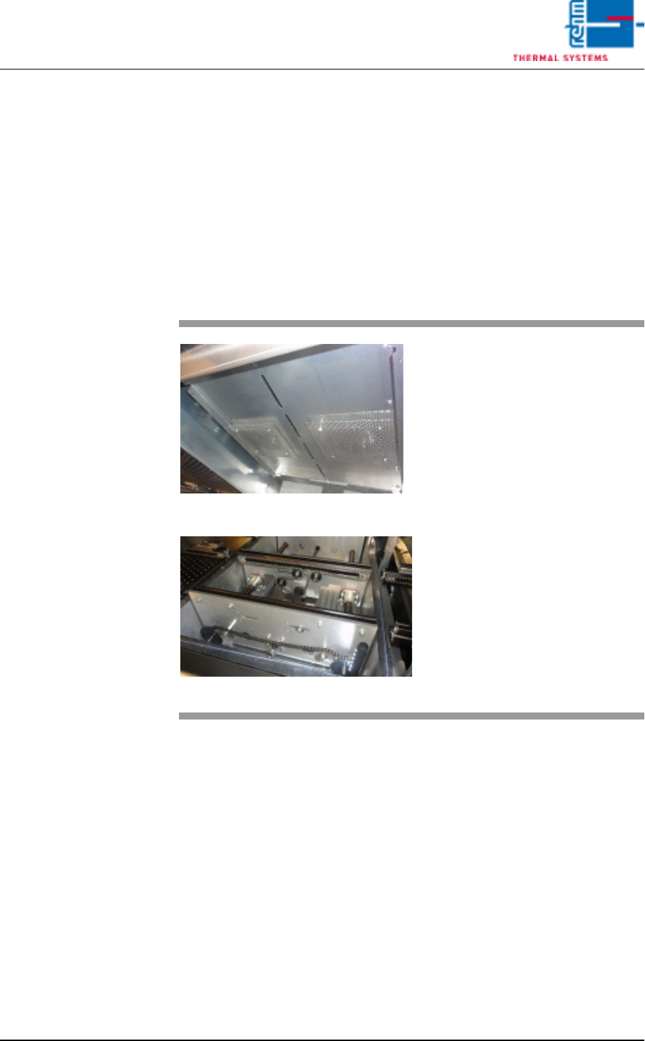
4.4.7 Vacuum zone
The vacuum chamber is located between the peak zone and cooling zone.
The processing time for a vacuum is made up of the individual steps.
The steps are as follows:
The product enters the vacuum chamber, the chamber closes, a vacuum is
drawn, the vacuum is vented, the chamber opens, and the product is
removed from the chamber.
If the vacuum process is not intended for a product, the zone can be used
as a peak zone
Fig. 4-29 Vacuum chamber
Fig. 4-30 Vacuum chamber
The modules enter into the machine
and are detected by an input sen-
sor.
Page 60 Vision XP+ VAC
4 Equipment
4.4 The Process Chamber
Operating Instructions
Version 1.5
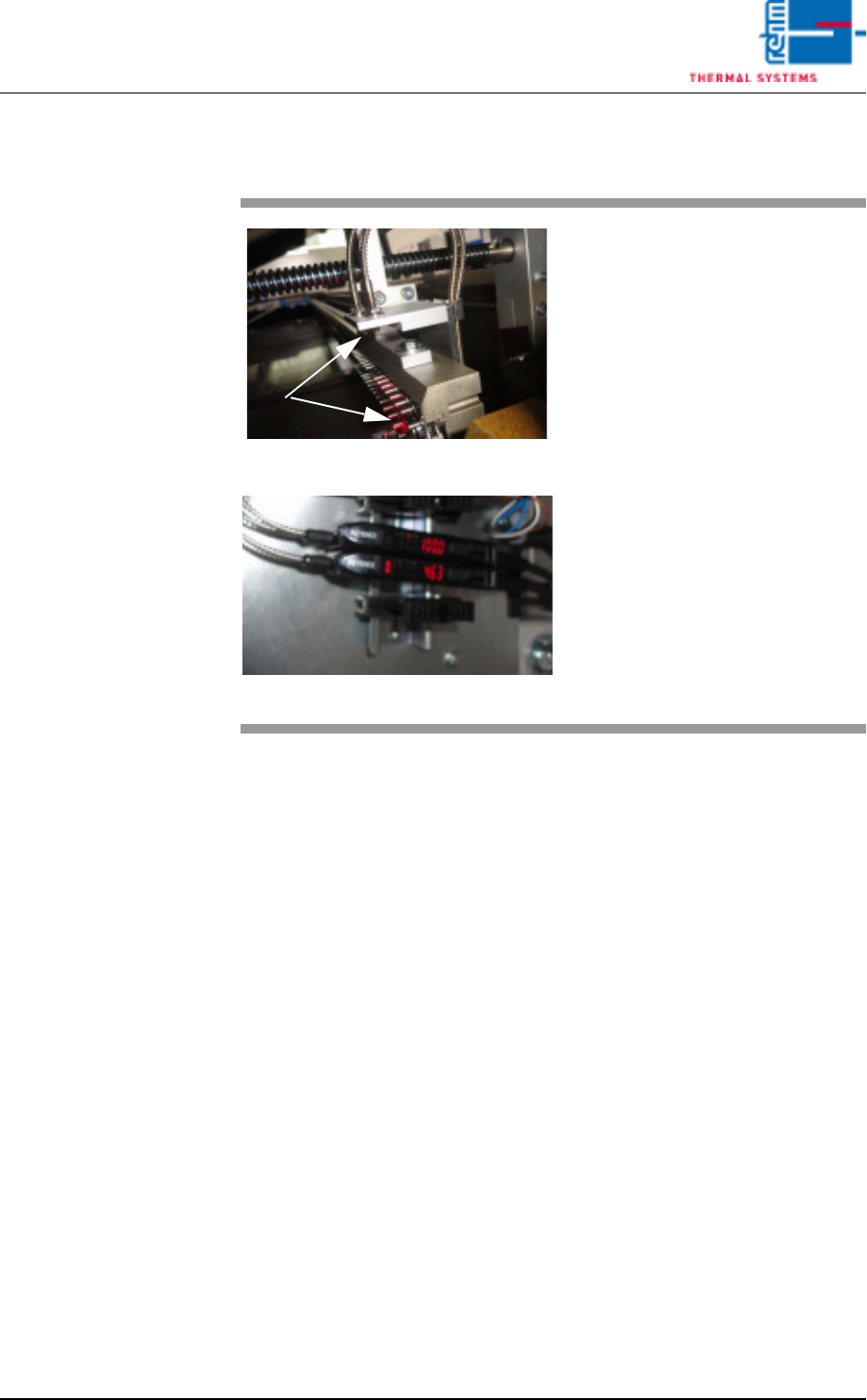
4.4.8 Sensors at the vacuum chamber
Fig. 4-31 Sensors at the Vacuum chamber
Fig. 4-32 Sensors at the Vacuum chamber
Optical fibre sensors are mounted
before and after the vacuum
chamber for PC board identification.
The sensors’ degree of soiling is
determined via the light intensity.
Cleaning and setting are described
in detail in the “Maintenance"
Chapter.
Vision XP+ VAC Page 61
4 Equipment
4.4 The Process Chamber
Operating Instructions
Version 1.5
4.4.9 The Cooling Tract
Note!
The transmission zone is located at the transition between the peak zone
and the cooling zone. A heating module is installed to the first cooling zone
which can be activated if necessary. The cooling gradient can be adjusted in
a highly flexible manner by means of temperature an frequency through the
use of this heating module. This infinitely adjustable influence on the cooling
gradient is necessary in order to assure stressless cooling for sensitive com-
ponents.
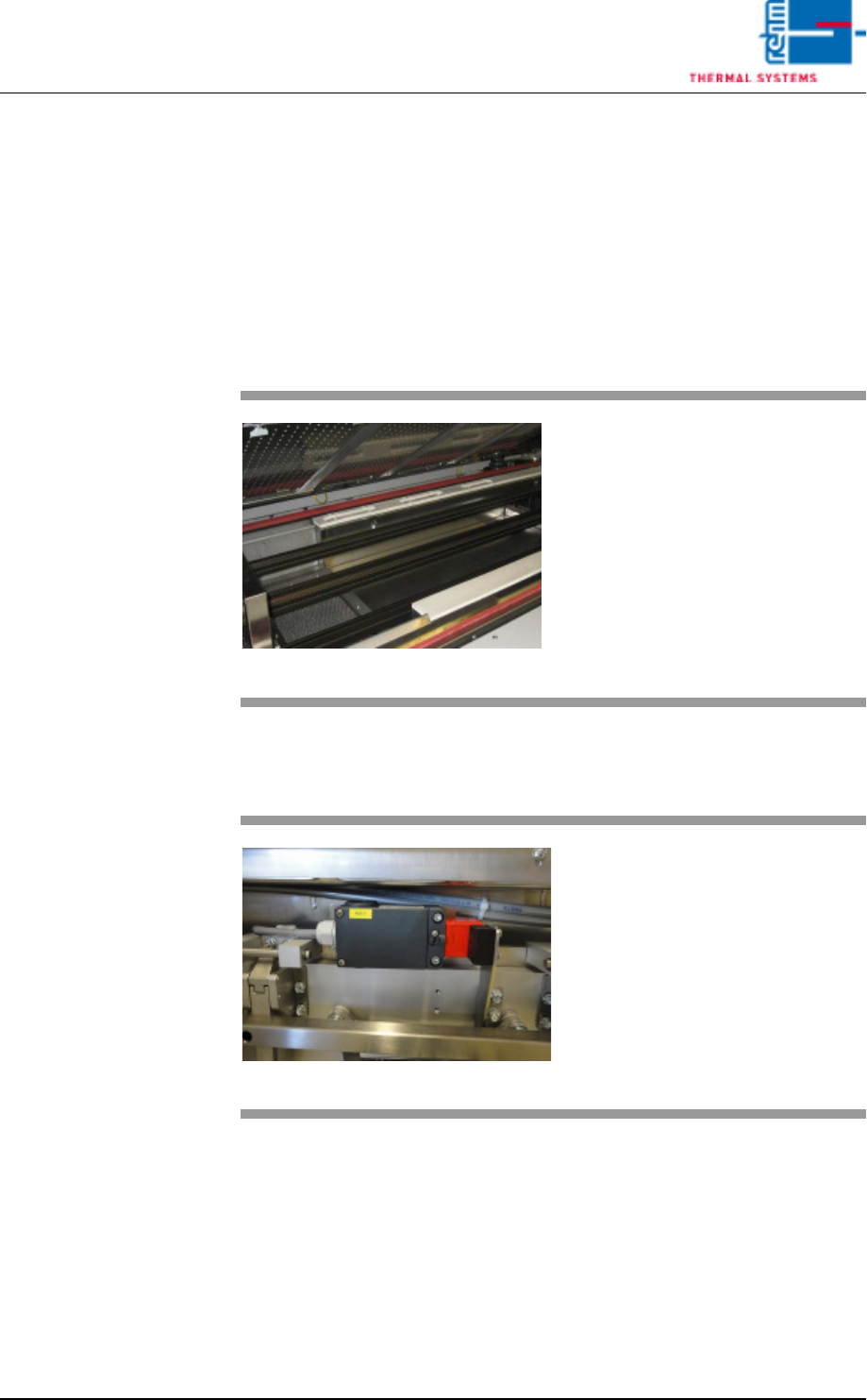
4.4.10 Safety switch cooling section VXP+
Fig. 4-33 The Cooling Tract
The PCBs are cooled down with the
help of nozzle sheets, which are lo-
cated above the conveyor system.
The required gas recirculation is
generated over blowers located at
the rear side of the system.
Fig. 4-34 Safety switch cooling section VXP+
As soon as the cooling section is
opened, the additional safety switch
in the cooling section is activated.
The fans of the cooling section are
switched off for safety-related pur-
poses.