OperationInstruction_Vsision XP.pdf - 第89页
V ISION XP+ V AC Page 81 5 Software 5.2 Main Window Operating Instructions V ersion 1.5 A) T i tle Bar The system design ation is shown here. B) Menu Bar V arious menus can be a ccessed which are r equired for system ope…
Page 80 VISION XP+ VAC
5 Software
5.2 Main Window
Operating Instructions
Version 1.5
Use of Color The utilized colors have the following meanings:
Green:Values are OK.
Orange:Values are too low.
Red:Values are too high.
Pink:The limit value has been reached. The system is shut down.
Blue:Action is required by the operator.
Entering Values Setpoints can be entered directly to the windows.
Setpoints are transferred directly to the controller when the enter key is
activated.
If the cursor is moved to the next entry field with the tab key or the mouse,
values are only displayed at the window. Setpoints do not become active
until the set button is clicked, by means of which they are transmitted to the
controller.
Buttons can be activated with the mouse, or they can be jumped to by
pressing the tab key and activated with the space bar.
5.2 Main Window
The main window and all available options are explained in this chapter.
Fewer functions may be included depending upon which system is used.
The system’s most important functions are integrated into the main window.
The various parameters can be viewed and changed.
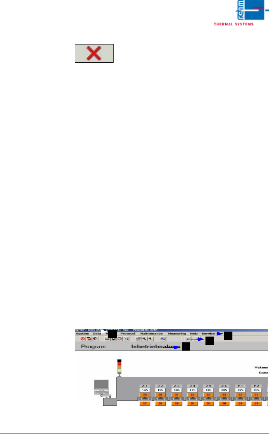
Fig. 5-9 Main Window (excerpt)
Fig. 5-8 Abort Button
The currently active window is closed when the Abort
button is clicked. The respective data are not saved
to memory.
Setpoints which have been entered, but have not yet
been acknowledged with the enter key (on the
keyboard), i.e. have not yet been transferred to the
controller, are lost. If you want to transfer the set-
points before exiting the window, click the
“Set” button first.
B
D
A
C
VISION XP+ VAC Page 81
5 Software
5.2 Main Window
Operating Instructions
Version 1.5
A) Title Bar
The system designation is shown here.
B) Menu Bar
Various menus can be accessed which are required for system
operation.
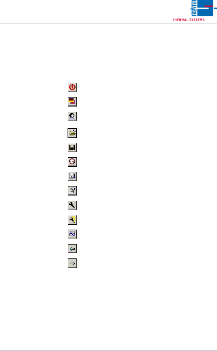
C) Toolbar
The following actions can be executed by clicking the appropriate icons:
D) The loaded program is displayed here, and optionally the loaded product
as well.
Exit Visu2
Select a language
Log on a new user
Load an existing program/product
Save a program/product or create a new one
Administer the program schedule
Reload system parameters
Display protocol
Display open maintenance tasks
Display pending maintenance tasks
Start the Rehm Recorder
Jump back one window
Jump forward one window
Page 82 VISION XP+ VAC
5 Software
5.2 Main Window
Operating Instructions
Version 1.5
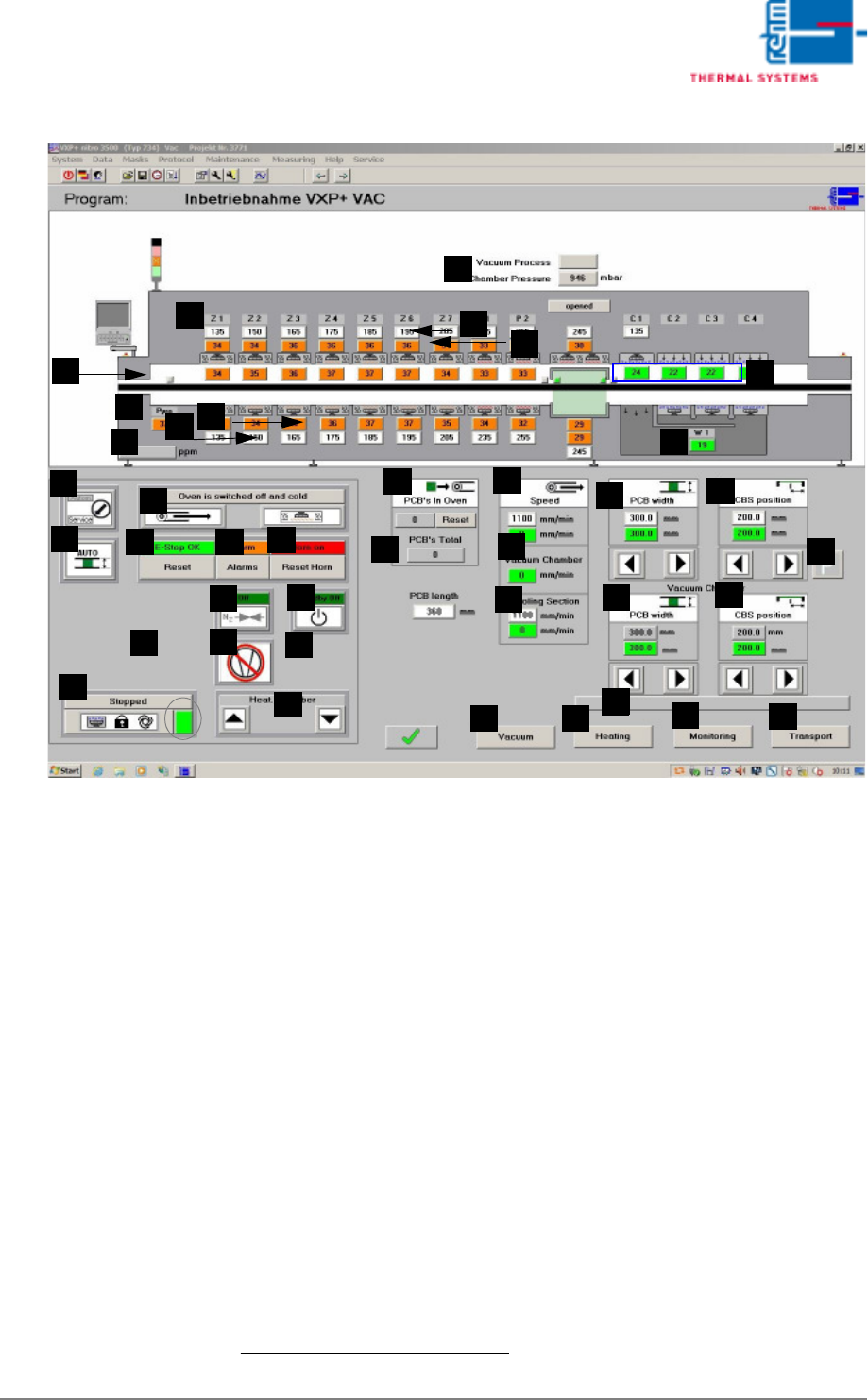
Fig. 5-10 Main Window
A) Designations of system zones
B) Temperature setpoints for the heaters above the conveyor are entered
here directly.
1
The values can be changed in the Heater window.
C) Temperature display for the heaters above the conveyor.
1
The desired tolerance can be selected with the Rel- and Rel+ parameters
in the Heating window.
D) Vacuum process
Grey display: Vacuum process is not running.
Green display: Vacuum process is running.
Chamber pressure display in mbar.
E) Temperature display for the monitoring in the process chamber.
1
The desired tolerance can be selected with the Rel- and Rel+ parameters
in the Monitoring window.
F) Temperature display for the cooling zone.
1
The desired tolerance can be selected with the Rel- and Rel+ parameters
in the Monitoring window.
Temperatures are controlled by means of temperature settings at the
cooling plant, or the external cooling system. Coolant water flow rate in-
F
E
G
H
B
A
C
D
I
J
Q
AA
Z
Y
X
W
V
U
T
S
R
P
O
N
M
L
K
AK
AI
AJ
AH
AG
AF
AB
AD
AC
AE
AM
AL
1. See also page 80, “Use of Color” and “Entering Values”.