OperationInstruction_Vsision XP.pdf - 第193页
V ISION XP+ V AC Page 185 7 Alarm Messages 7.15 Speed (option) Operating Instructions V ersion 1.5 7.15 Speed (o ption) 7.16 Stands till Monitor ing (opti on) Fig. 7-1 5 Con veyor C hain The conveyor cha in is too slow o…
Page 184 VISION XP+ VAC
7 Alarm Messages
7.13 Power Supply
Operating Instructions
Version 1.5
After closing the condensate trap, it must be locked again with the same but-
ton. The fans do not start back up again until the condensate trap has been
locked.
If the „Condensate Trap Error“ alarm cannot be reset with the „Reset Alarm“
button, the system must first be switched to the service mode and the „Open
Condensate Trap“ button must be clicked. As a result, the condensate trap
fans are no longer activated.
If the „Open Condensate Trap“ button indicates that the fans are at a stand-
still („Stopped“), the lock can once again be secured with the help of the
„Open Condensate Trap“ button, and the fans can be operated again. „Run-
ning“ should then appear at the display and the alarm should be reset.
7.13 Power Supply
7.14 Cooling Tract Circulation
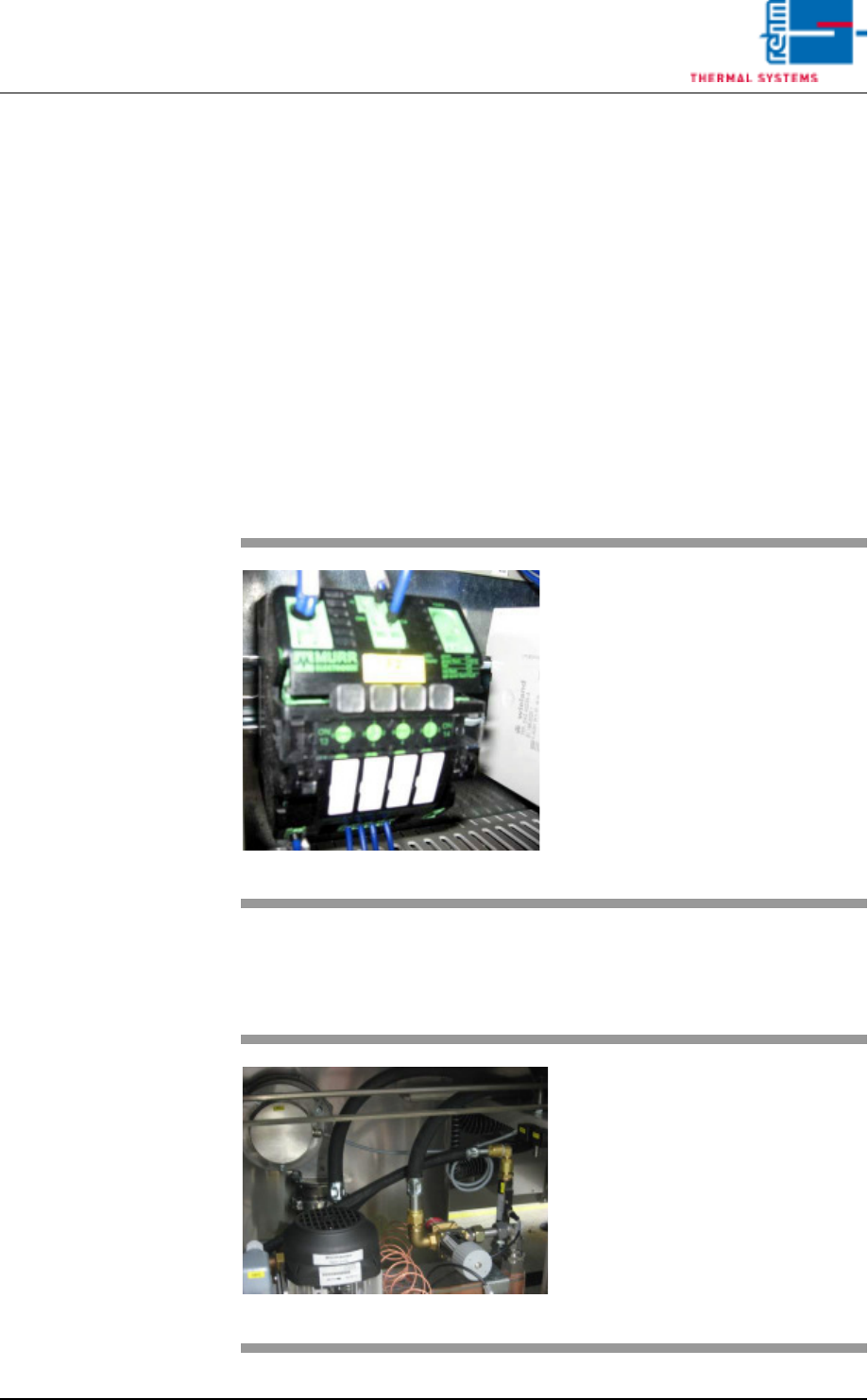
Fig. 7-13 Power Supply Fuse
The power supply alarm appears
when the fuse blows.
Procedure:
1. The triggered fuse is identified
by means of a red LED.
2. Press the red-shining button to
reset the error.
Fig. 7-14 Cooling tract circulation
The fan is supervised for recircula-
tion. If there are malfunctions, an
alarm will be released.
VISION XP+ VAC Page 185
7 Alarm Messages
7.15 Speed (option)
Operating Instructions
Version 1.5
7.15 Speed (option)
7.16 Standstill Monitoring (option)
Fig. 7-15 Conveyor Chain
The conveyor chain is too slow or
too fast relative to the selected
Rel+/- values.
Possible causes:
• The conveyor has been overload-
ed.
• Conveyor chain lubrication has
failed.
• The drive motor (A) is defective.
• The slip clutch (B) is loose.
• The conveyor impulse is not right.
Caution!
The work steps to be completed in-
volve danger of pinching.
B
A
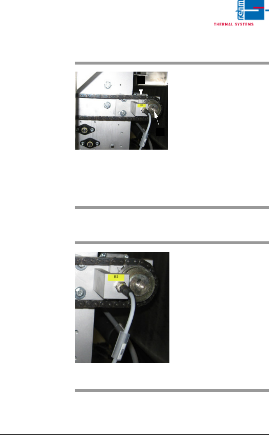
Fig. 7-16 Band pulse sensor
The transport chain doesn't move,
although the drive motor is running.
The friction clutch rotates freely.
Procedure:
• Check to see whether or not the
conveyor chain is running. Re-
move any jammed parts.
• Check the slip clutch for correct
adjustment.
• Check the chain sprocket sensor
for correct functioning.
• Inspect the drive motor.
Caution!
The work steps to be completed in-
volve danger of pinching.

Page 186 VISION XP+ VAC
7 Alarm Messages
7.17 Minimum Temperature Tolerance Fallen Short
Off
Operating Instructions
Version 1.5
7.17 Minimum Temperature Tolerance Fallen Short Off
One or more actual temperature values have fallen below the Rel- tolerance
limit.
Possible causes:
• Too little heating power (Y max.) has been selected at the heater settings.
• The heater controller is defective, or has failed.
• The system is in the warm-up phase.
Procedure:
• Determine whether or not available heating power is adequate.
• The modul thermocouple is not plugged in correctly, or has failed.
7.18 Maximum Temperature Limit Value Exceeded
One or more actual temperature values have exceeded the specified tem-
perature limit MAX.
Possible causes:
• A temperature sensor is defective.
• Temperature setpoints have been set too high (close to or greater than the
upper limit value). A difference of at least 10 Kelvin is required.
• The modul thermocouple is not plugged in correctly, or has failed.
Procedure:
• Inspect the temperature sensor.
• Check the temperature setpoints.
• Determine whether or not such a high temperature is necessary. If so, de-
termine whether or not the upper limit value can be adjusted.
• Check the temperature controller settings.
• The coolant water flow rate is inadequate.
7.19 Maximum Temperature Tolerance Exceeded
One or more actual temperature values have exceeded the specified Rel+
tolerance limit.
Possible causes:
• The physical limits of the heating zones have been exceeded.
• The coolant water flow rate is inadequate.
Procedure:
• Check the selected temperature profile.