OperationInstruction_Vsision XP.pdf - 第94页
Page 86 V ISION XP+ V AC 5 Software 5.2 Main Window Operating Instructions V ersion 1.5 port is released again only after th e process chamber i s opened and closed. V) Vacuum active/i nactive If the button i s active, t…
VISION XP+ VAC Page 85
5 Software
5.2 Main Window
Operating Instructions
Version 1.5
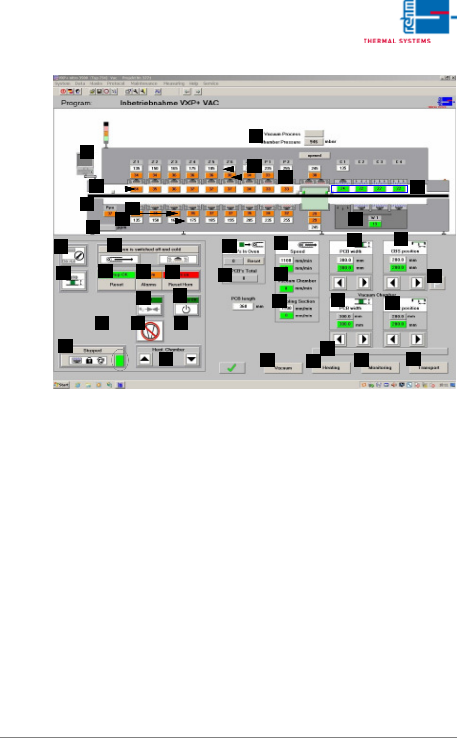
Fig. 5-11 Main Window
T) Standby mode
The standby mode is an energy saving mode. It’s activated as soon as
the system is empty, assuming there are no pending requests for new
PCBs.
An on-time count-down is initialized when the standby mode is activated.
After the specified time has elapsed, fan frequency is reduced.
If the standby mode is active and a request occurs for a new PCB, an off-
time count-down is started. After the specified time has elapsed, fan fre-
quency is restored to it original value.
The standby mode can be manually started or ended with the standby
button. The text displayed above the button indicates the current status
of the standby mode. The following statuses are possible:
- Standby off: The standby mode is deactivated.
- Empty conveyor: The conveyor is run until it is empty.
- Start-up count-down: Power-up delay time is running.
- Standby on: The standby mode is active.
- Stop count-down: Shutdown delay time is running.
U) Pin-in-Paste
Is the function active and the temperature in the first zone under 160 °C
t, the heating and the blower are switched off in the first bottom zone. The
supervision of the motor in this zone is no longer active. With program
change from „Pin in Paste“ to normal or from „Pin in Paste“ to „Pin in
Paste“ the transport adjustment is locked. The transport adjustment is
locked as long as the function is active. With program change the trans-
F
E
G
H
B
A
C
D
I
J
Q
AA
Z
Y
X
W
V
U
T
S
R
P
O
N
M
L
K
AL
AH
AB
AF
AG
AJ
AI
AC
AD
AE
AM
AK

Page 86 VISION XP+ VAC
5 Software
5.2 Main Window
Operating Instructions
Version 1.5
port is released again only after the process chamber is opened and
closed.
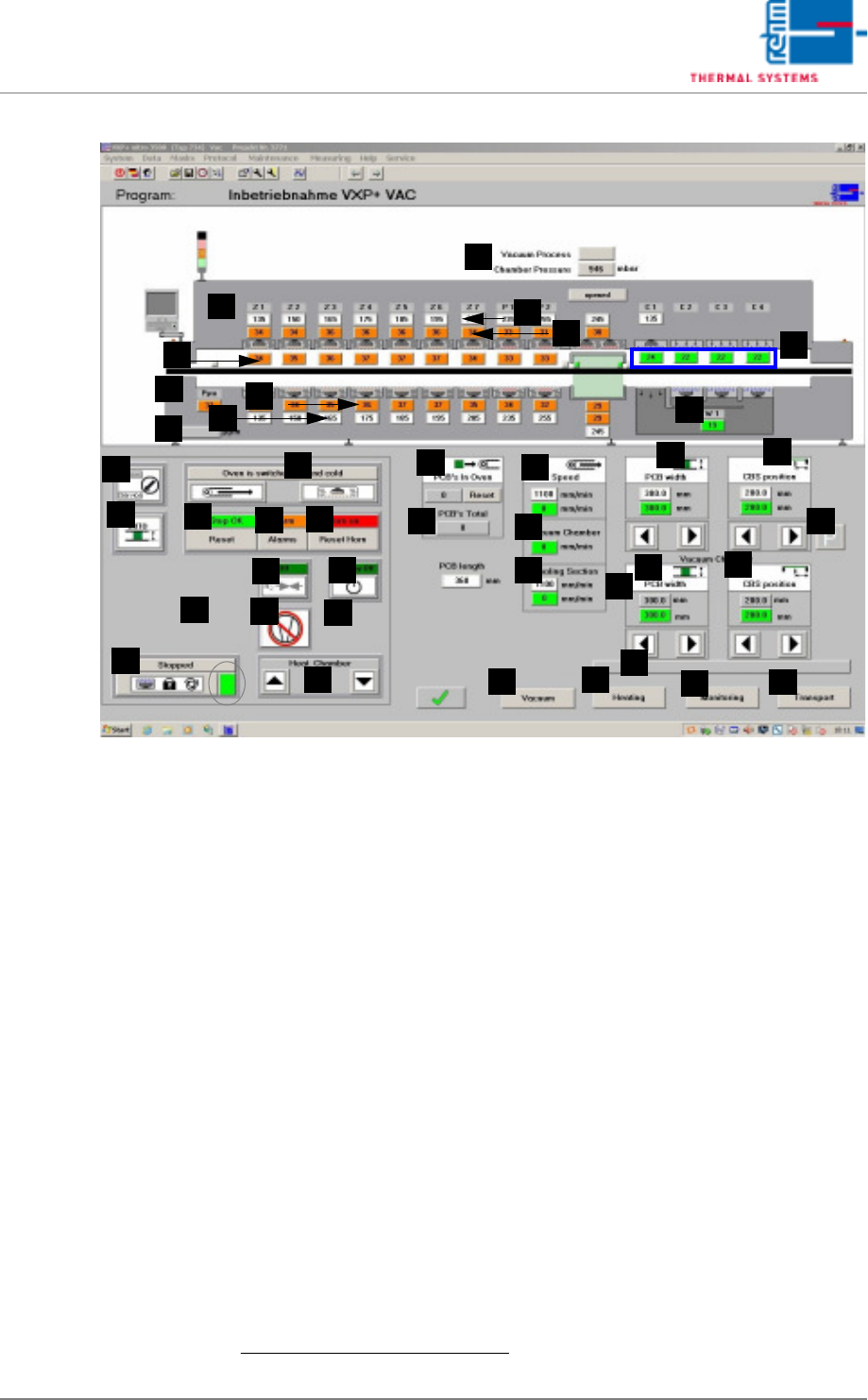
V) Vacuum active/inactive
If the button is active, the vacuum mode is switched on.
If the button is inactive, the vacuum mode is switched off.
W) Stopper up/down
Down: The outlet stoppers have been advanced to the bottom position.
PCBs can be discharged from the system in an unobstructed fashion.
Up: The outlet stoppers are controlled by the outlet interface. The PCBs
are stopped as long as no enabling signal is received from the down-
stream module, and cannot be discharged from the system.
X) Open/Close Process Chamber
These buttons are only enabled when the operating mode switch has
been set to service. The process chamber is opened with the left-hand
button, and closed with the right-hand button. An acoustic signal is gen-
erated by the horn while the process chamber is being closed.
Y) Display for Number of PCBs
PCB´s in Oven: indicates the number of assemblies in the system. The
indication is grey as long as the system is unloaded and operated without
load. It is green when the system is loaded. The indication is yellow, when
the system is unloaded and not operated yet without load.
The system is operated without load, when the last board is transported
out of the system and afterwards the pulse duration is expired under „Buf-
fer Conveyor empty“ in the mask Interface (see chapter 5.5.7, page 116).
The conveyor can only be trammed, when the indication is grey.
Total PCBs: displays the number of PCBs which have been produced
since the current program was loaded. The counter is reset when system
software is exited, or when a new program is loaded.
One PCB can be subtracted from the displayed number of PCBs in the
oven by pressing the Reset key. If this button is pressed and held for
more than 5 seconds, the counter is reset to 0. This function is only en-
abled when the operating mode switch has been set to service.
VISION XP+ VAC Page 87
5 Software
5.2 Main Window
Operating Instructions
Version 1.5
Fig. 5-12 Main Window
Z) PCB's placing
With this input field the display Total PCBs may be set at a value from
which counting starts to continue.
Procedure:
– Put in desired value and as soon as the display Total PCBs states
the set value, enter „0“.
– When entering „1“ or „load program“ the display will be set back to
„0“.
AA)Transport speed of the vacuum chamber
Entering a new target value (white box) changes the transport speed.
The actual value is displayed in the box below.
1
AB)Vacuum chamber
Speed display in vacuum mode; this can be adjusted separately.
AC)Cooling section for vacuum mode
The speed in vacuum mode can be adjusted separately. Entering a new
target value (white box) changes the speed in the cooling section. The
actual value is displayed in the box below.
AD)Conveyor Width Adjustment
Conveyor width is changed by entering a new setpoint (white field).
1
As
a prerequisite, the conveyor adjustment switch must be set to “Auto”, the
heaters must display values of at least 90° C (adjustable) and there may
F
E
G
H
B
A
C
D
I
J
Q
AA
Z
Y
X
W
V
U
T
S
R
P
O
N
M
L
K
AL
AH
AB
AF
AG
AJ
AI
AC
AD
AE
AM
AP
AK
1. Siehe hierzu auch page 80, “Use of Color” bzw. „Werte eintragen“.