OperationInstruction_Vsision XP.pdf - 第65页
Vision XP+ V AC Page 57 4 Equipment 4.4 The Process Chamber Operating Instructions V ersion 1.5 4.4.5 N itrogen Lock at the Inlet Fig. 4-2 5 Nitrog en Loc k at the Inl et The nitrogen lock functions as a thermal barrier …
Page 56 Vision XP+ VAC
4 Equipment
4.4 The Process Chamber
Operating Instructions
Version 1.5
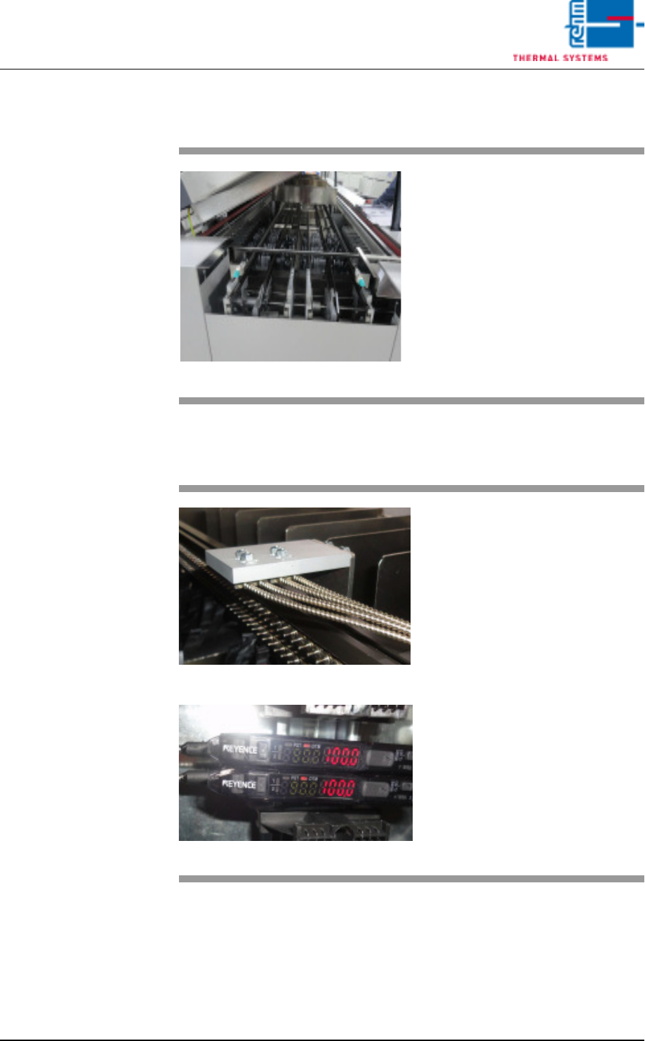
4.4.3 Inlet Area
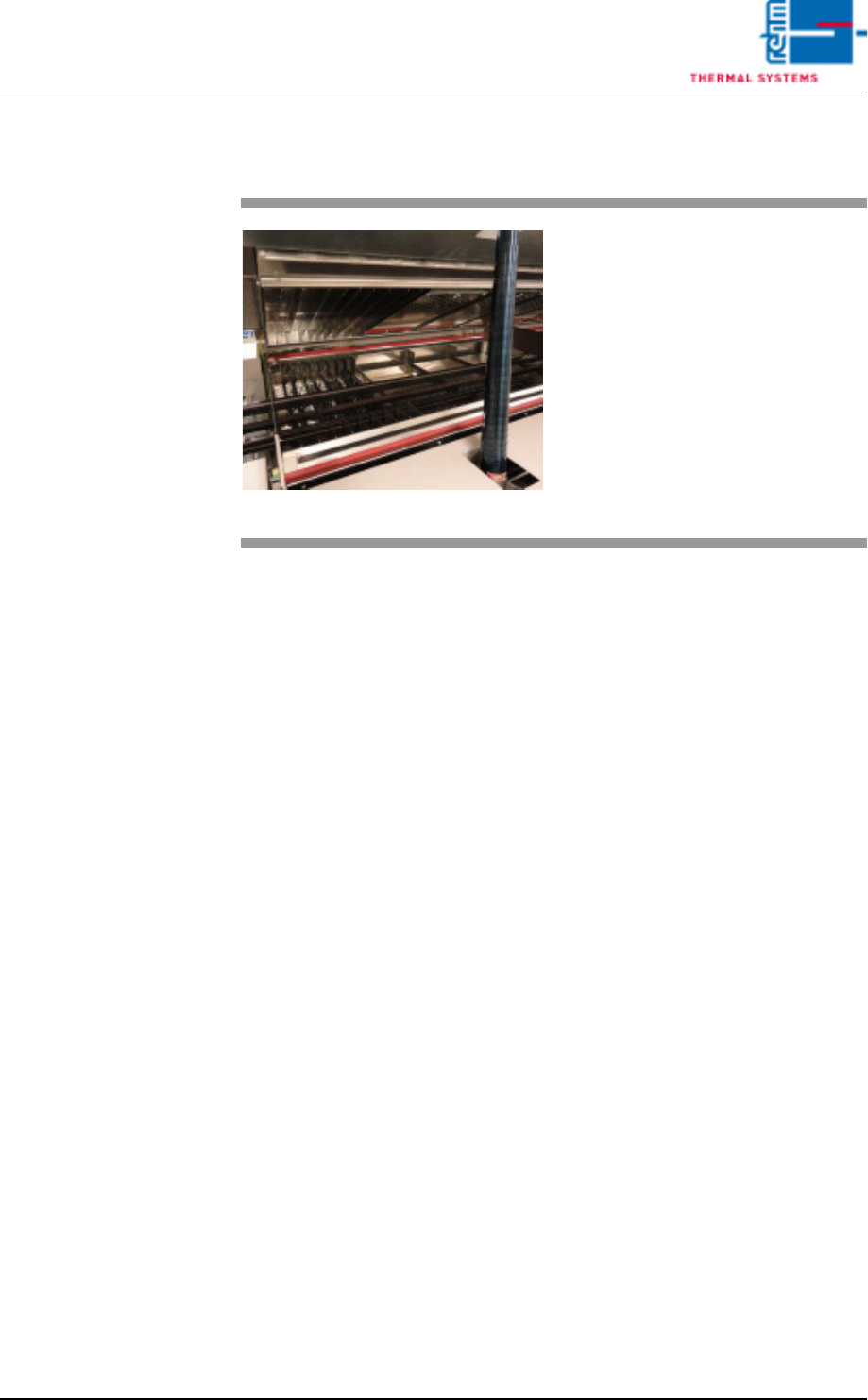
4.4.4 Sensors in the inlet area
Fig. 4-22 Inlet Area
The inlet area includes the adjusting
mechanism for the conveyor sys-
tem, as well as the sensor for the in-
terfaces and for counting PCBs in
the system.
Escaping soldering vapors are
drawn off into a removable metallic
gauze filter located in the cover.
Fig. 4-23 Sensors at the Inlet area
Fig. 4-24 Sensors at the Inlet area
The plant infeed has an optical fibre
sensor for PC board identification.
The degree of soiling of the sensor
is determined via the light intensity.
Cleaning and setting is described in
detail in the “Maintenance" Chapter.
Vision XP+ VAC Page 57
4 Equipment
4.4 The Process Chamber
Operating Instructions
Version 1.5
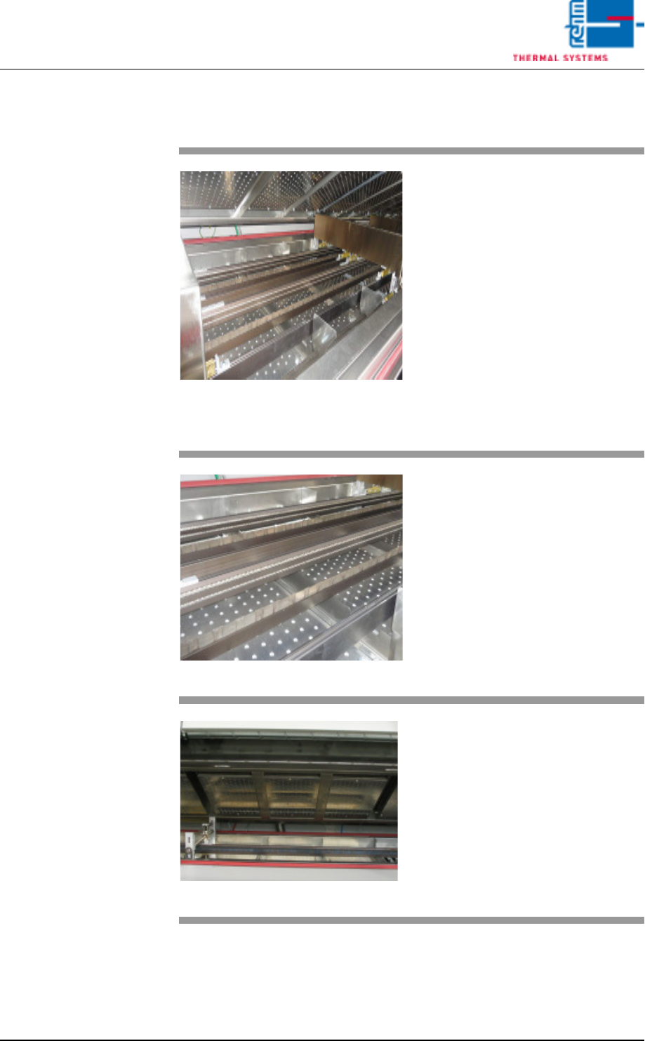
4.4.5 Nitrogen Lock at the Inlet
Fig. 4-25 Nitrogen Lock at the Inlet
The nitrogen lock functions as a
thermal barrier between the work
area at the inlet and the heating
chamber.
It is comprised of flow barriers, and
it improves the oxygen-free state of
the air.
Page 58 Vision XP+ VAC
4 Equipment
4.4 The Process Chamber
Operating Instructions
Version 1.5
4.4.6 Heating Chamber
Fig. 4-26 Preheating
Preheating is distributed over sever-
al heating zones which are located
above and below the conveyor sys-
tem. The heating zones can be ad-
justed independent of each other.
The atmosphere in the individual
zones is circulated by means of
fans, heated up with tubular heaters
and returned to the process via noz-
zle sheets.
Temperature is regulated with the
help of temperature sensors which
are installed in direct proximity to
the tubular heaters.
Fig. 4-27 Preheating at the Bottom
Simultaneous heating of the PCBs
from above and below in the pre-
heating zone allows for the solder-
ing of PCBs with especially high
masses just as quickly as normal
PCBs.
Fig. 4-28 Peak Zone
The peak zone (soldering zone) is
subdivided into heat zones which
are located above and below the
conveyor system. They can be ad-
justed independent of each other.
Due to the fact that more heating
power is required in the peak zone
than for preheating, tubular heaters
with greater heating power are in-
stalled here for the hot gas areas.