OperationInstruction_Vsision XP.pdf - 第126页
Page 1 18 V ISION XP+ V AC 5 Software 5.5 The Masks Menu Operating Instructions V ersion 1.5 5.5.8 Fifo Interface (optional) Fig. 5-4 7 Fifo Int erface With the Fifo option there is a PCB buffer behind the oven . The buf…

VISION XP+ VAC Page 117
5 Software
5.5 The Masks Menu
Operating Instructions
Version 1.5
G) Buffer Conveyor empty
After covering the inlet light barrier the transport adjustment for the sum
of conveyor length and buffer transport empty is decelerated. After enter-
ing 0, the function is deactivated. Is the value higher than „0“, the function
is active. With active function each board remains in the oven until it has
moved through the complete oven, plus the preset safety value. Indepen-
dently, if the board was deleted or reset manually only afterwards the
oven is unloaded.
H) Fifo (option)
It indicates if the PCB buffer at the outlet is active.
I) Barcode (option)
It indicates if the Barcode Scanner at the inlet is active.
J) Pin in Paste (option)
It indicates if the Pin in Paste-function is active.
K) No demand/demand at the inlet
It indicates that the preceding module wants to pass on the assembly
group to the oven.

Page 118 VISION XP+ VAC
5 Software
5.5 The Masks Menu
Operating Instructions
Version 1.5
5.5.8 Fifo Interface (optional)
Fig. 5-47 Fifo Interface
With the Fifo option there is a PCB buffer behind the oven. The buffer is re-
sponsible that all boards are collected correctly in the oven also when sub-
sequent machines stopped.
In case of a failure the oven cannot be stopped as otherwise the boards burn
up. If no buffer is available and the subsequent machine doesn't take over
the boards, they move on top of each other in the cooling zone.
To ensure that the buffer can take up the boards at any time, the buffer locks
the oven inlet when the number of boards in the oven has achieved the num-
ber of free spots in the buffer. In order that it works two signals have to be
exchanged between the oven and the buffer, one in order that the buffer can
lock the oven and the second in order that the oven can inform the buffer
about the number of boards (an impulse per board). The signal for inlet lock-
ing is wire break-proof, with 24V the oven inlet is free, if there is no signal –
the oven inlet is locked. If the buffer is removed subsequently from the line
please ensure that 24V are on the interface as otherwise the oven inlet is
locked permanently.
VISION XP+ VAC Page 119
5 Software
5.5 The Masks Menu
Operating Instructions
Version 1.5
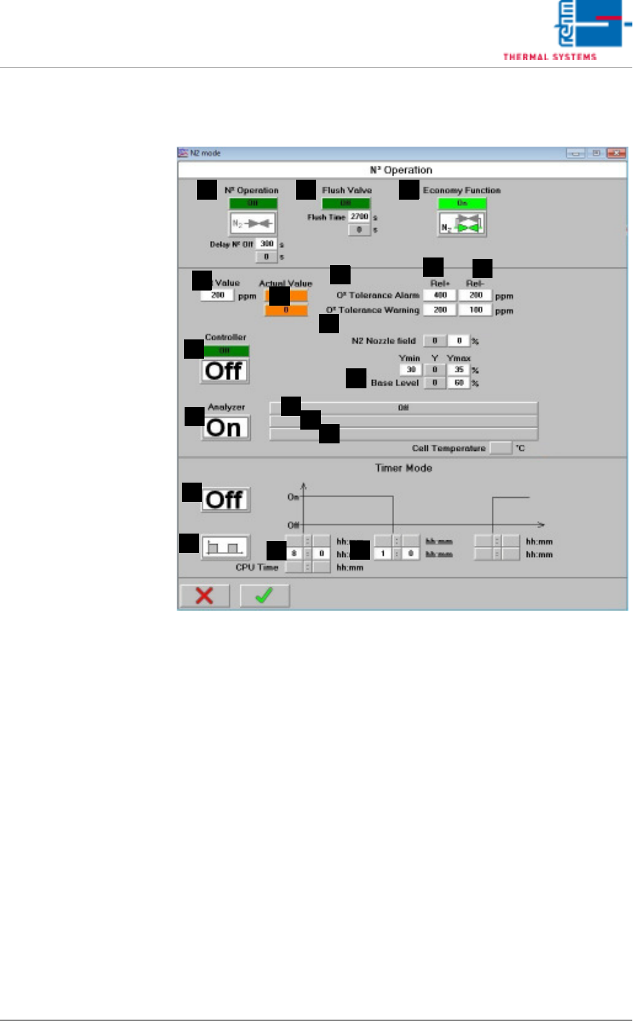
5.5.9 N2 Operating Mode
Fig. 5-48 N2 Operating Mode
Note!
Timer Mode:
The timer function is deactivated when the nitrogen control is working.
A) N2 Operation
On: Soldering is executed in a nitrogen atmosphere, servo-valves are
open. Off: Soldering is executed in air, servo-valves are closed in a time
delayed fashion. It is also possible to enter after how much delay time in
seconds nitrogen operation when switching off the heating is deactivated.
B) Flush Valve
After nitrogen operation has been activated, a scavenging valve is addi-
tionally opened for an adjustable period of time. Specified time can be ad-
justed here, and elapsed time can be monitored. Valve status is
displayed. The process chamber is opened, N2 operation is stopped im-
mediately. The purging phase is started over from the beginning after the
system has once again been completely closed.
C) Saving function (optional)
The economy mode option monitors the system’s loading status. An ad-
ditional control valve is opened after nitrogen operation has been activat-
CBA
F
Q
J
G
K
D
R
S
O
P
N
E
M
L
H
I