OperationInstruction_Vsision XP.pdf - 第73页
Vision XP+ V AC Page 65 4 Equipment 4.4 The Process Chamber Operating Instructions V ersion 1.5 4.4.16 A ctive cooling module (option) 4.4.17 I nternal T emperature Monitoring (option) Fig. 4-4 2 Ac tive cooling module A…
Page 64 Vision XP+ VAC
4 Equipment
4.4 The Process Chamber
Operating Instructions
Version 1.5
4.4.14 Nitrogen Lock at the Outlet
4.4.15 Outlet Area
Fig. 4-40 Nitrogen Lock at the Outlet
Nitrogen lock separates the cooling
section from outlet area.
It is comprised of flow barriers, and
it improves the oxygen-free state of
the air.
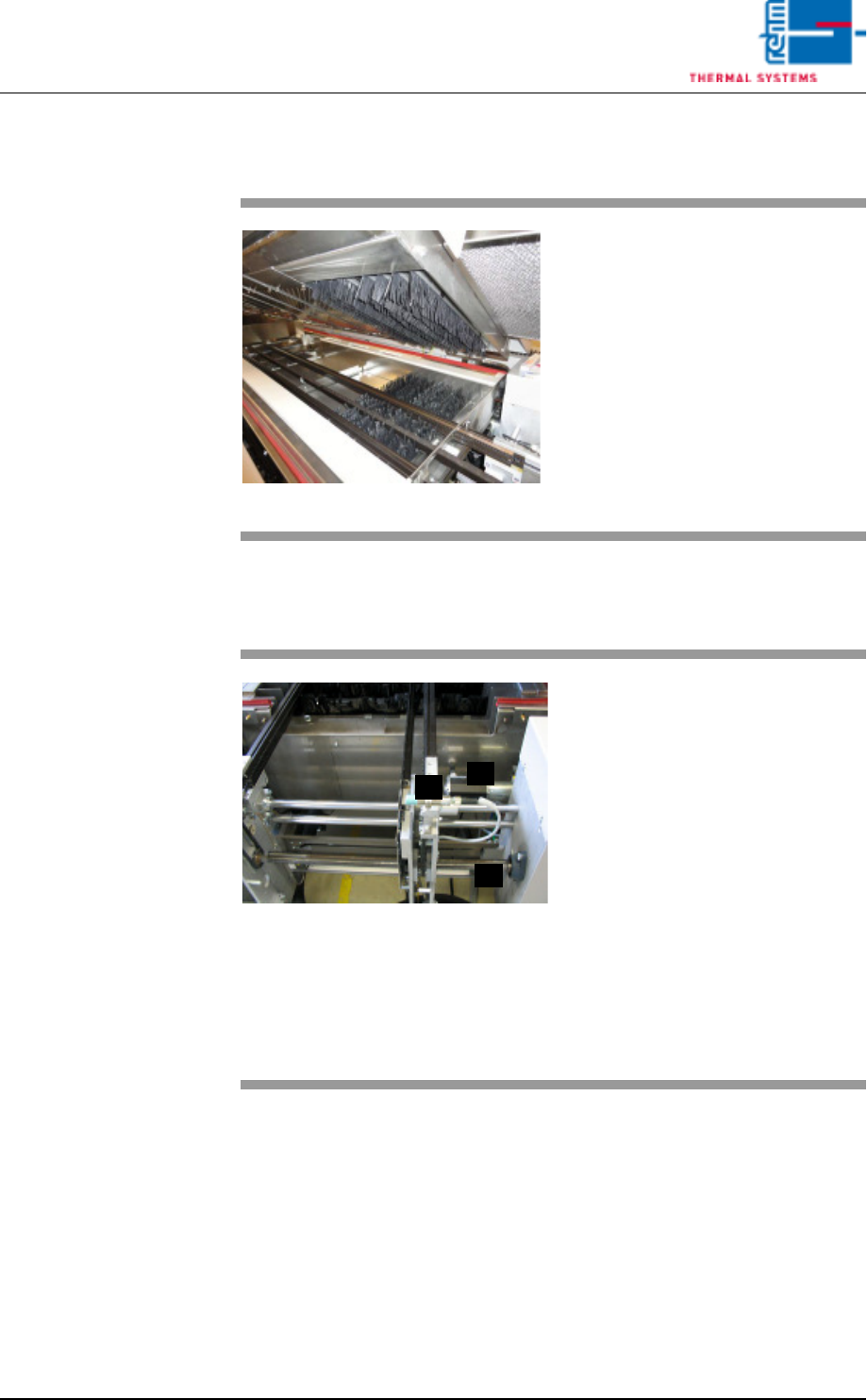
Fig. 4-41 Outlet Area with ultrasonic sensor
The outlet area includes:
A) The sensor for the interfaces and
for counting all PCBs which have
been soldered since the system
was switched on.
B) The drive motor with slip clutch
for the PCB conveyor
C) The adjusting mechanism for the
conveyor system
D) The pulse sensor (located at the
rear of the system)
Escaping soldering vapors are
drawn off into a removable metallic
gauze filter located in the cover.
C
B
A
Vision XP+ VAC Page 65
4 Equipment
4.4 The Process Chamber
Operating Instructions
Version 1.5
4.4.16 Active cooling module (option)
4.4.17 Internal Temperature Monitoring (option)
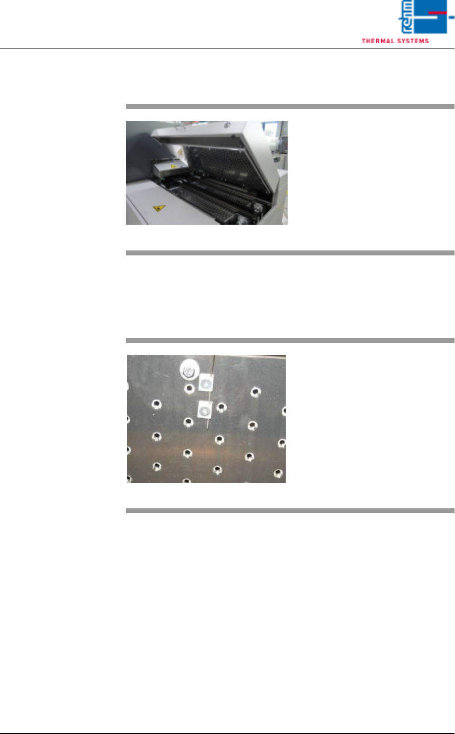
Fig. 4-42 Active cooling module
An active cooling module can also
be fitted at the outlet of the system
to enable additional cooling of sub-
assemblies.
Fig. 4-43 Internal Temperature Sensor
Temperature is monitored in the in-
dividual heat zones by means of
sensors which are located directly at
the conveyor level. A sensor for
measurement of the interior temper-
ature is connected at each nozzle
field.
Tolerances and limit values which
are intended to trigger an alarm can
be selected as desired by the user.
Page 66 Vision XP+ VAC
4 Equipment
4.4 The Process Chamber
Operating Instructions
Version 1.5
4.4.18 Process Chamber Elevator
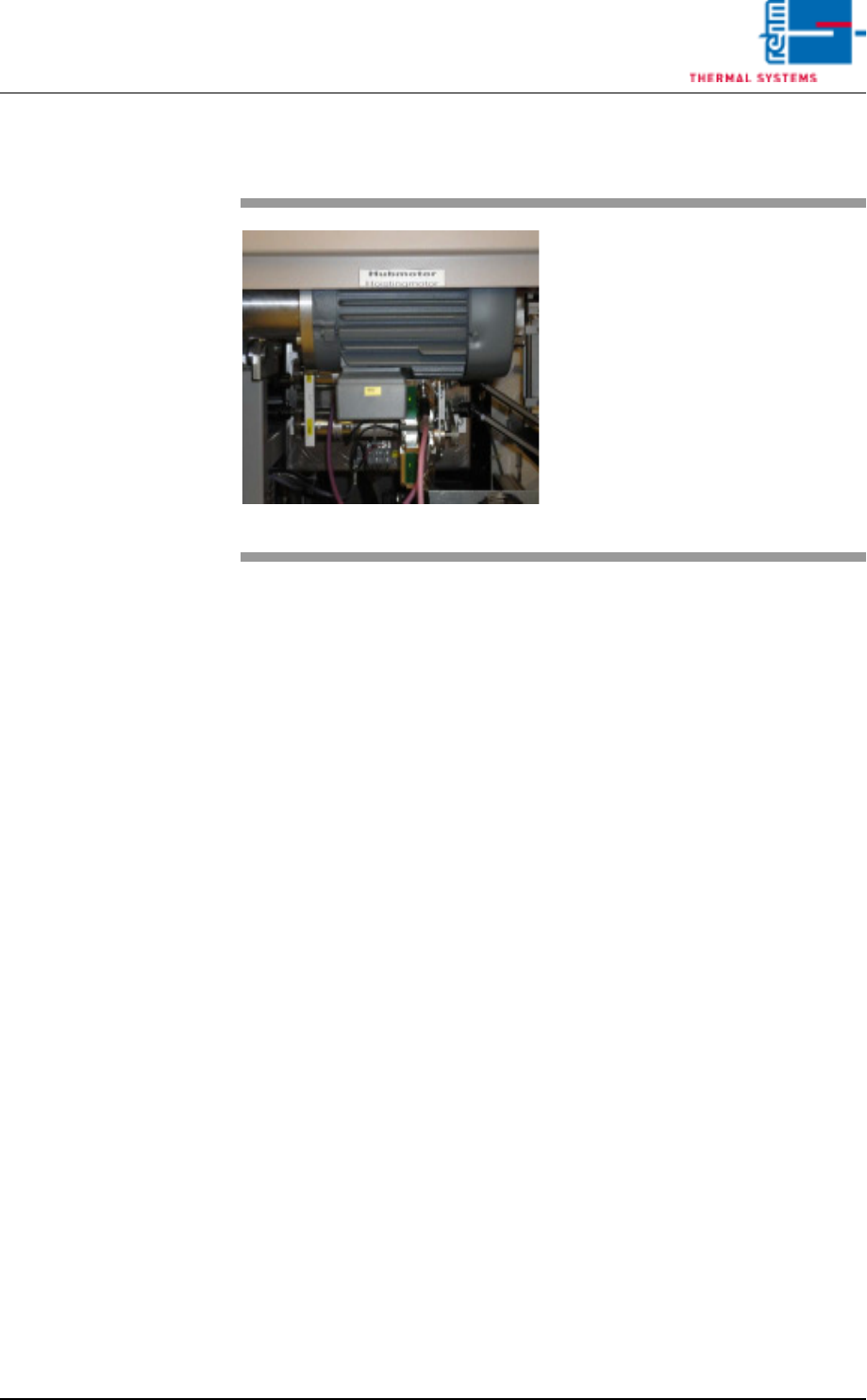
Fig. 4-44 Process Chamber Elevator
A motor drives the spindles, which
in turn lift the process chamber.
Positioning of the process cham-
bers is initialized by buttons on the
main screen.
See also chapter Software,
Fig. 5-11 Main Window, on page 85.