OperationInstruction_Vsision XP.pdf - 第197页
V ISION XP+ V AC Page 189 7 Alarm Messages 7.27 Cooling W ater failure (option) Operating Instructions V ersion 1.5 7.27 Coolin g W ate r failure (option) Fig. 7-1 8 Coo ling Syste m Comp onents Fig. 7-1 9 Coo ling Syste…

Page 188 VISION XP+ VAC
7 Alarm Messages
7.23 Outlet Interface (Option-Siemens-Interface)
Operating Instructions
Version 1.5
7.23 Outlet Interface (Option-Siemens-Interface)
The PCB is at the outlet interface, but the downstream module does not al-
low enabling, or it does not acknowledge the previous PCB.
Procedure:
Assure that the downstream module is enabled.
7.24 Error Circuit
A downstream device is not ready for operation. Enabling is not allowed by
the inlet interface.
Possible causes:
• Error at the outlet.
• The magazine at the outlet is full.
7.25 PCB accumulation inlet
accumulation at inlet sensor.
7.26 Cooling section volume flow malfunction
The “Cooling section volume flow” alarm will trigger should volume flow be
out of tolerance.
Procedure:
Check all filters incl. cooling section filter F9 for dirt and replace if
necessary.
VISION XP+ VAC Page 189
7 Alarm Messages
7.27 Cooling Water failure (option)
Operating Instructions
Version 1.5
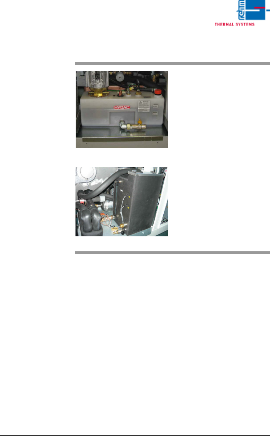
7.27 Cooling Water failure (option)
Fig. 7-18 Cooling System Components
Fig. 7-19 Cooling System Components CN
Possible causes:
• The cooling water pump on the
water tank cannot be started or is
defective.
• The pressure sensor is defective.
Procedure:
• Inspect all tubing and connec-
tions to the pump.
• Inspect the sensor and the cool-
ing water pump and replace if
necessary.
Page 190 VISION XP+ VAC
7 Alarm Messages
7.28 Water amount is too low (option)
Operating Instructions
Version 1.5
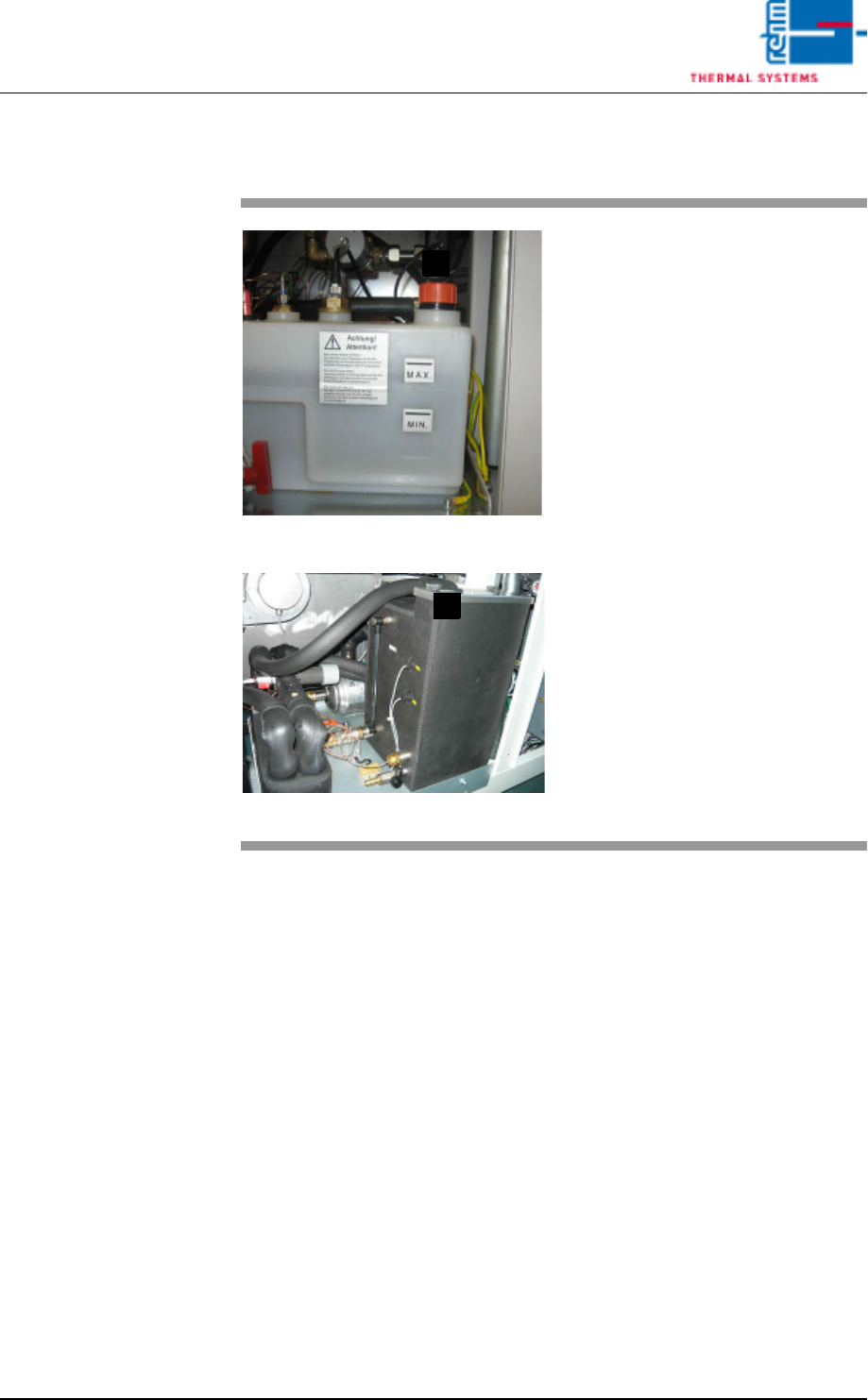
7.28 Water amount is too low (option)
7.29 Water Leak (option)
Possible causes:
• The water system has a leak.
• There’s no water in the tank.
• The sensor is defective.
Procedure:
• Inspect all tubing and connections within the water system, and repair if
necessary.
• Fill the water tank.
• Inspect the sensor and replace if necessary.
Fig. 7-20 Tank with Water Level Sensor
Fig. 7-21 Tank with Water Level Sensor CN
Possible causes:
• There is too little water in the tank.
• The sensor is defective.
Procedure:
• Fill in the mixture of cooling water
in (E) by means of a watering can.
• Inspect the sensor.
E
E