OperationInstruction_Vsision XP.pdf - 第37页
Vision XP+ V AC Page 29 3 From Tr ansport to Initial Start-Up 3.1 T ransport Configuration and T ransport Operating Instructions V ersion 1.5 3 From T ransport to Initial Start-Up This chapte r explains how the sys tem i…

Page 28 Vision XP+ VAC
2 Operating Safety
2.11 Training
Operating Instructions
Version 1.5
2.11 Training
The safety regulations specify that all employees must be trained. However,
due to the fact that not all employees are exposed to the same degree of
danger, extensive training is not necessary for each individual.
In order to determine how much training any given employee requires, each
employee is assigned to one of three different categories, each with its own
level of training:
1. Authorized Employees
These employees install the locks and warning signs, and perform
maintenance and service work. They must have well founded
knowledge of energy regulation for this reason.
Firstly, they must be able to pinpoint and measure all energy sources.
They must also be capable of locating energy sources which cannot be
recognized as such at first glance, for example electrical energy, kinetic
energy, chemical energy and thermal energy. After authorized
employees have mastered these tasks, they must be taught to enable,
regulate and release energy in a safe manner.
2. Effected Employees
This classification includes employees who operate the machines or
components which are to be deactivated. Employees who work in an
area with equipment which must be locked, or which must be identified
as locked, are included in this classification as well. These employees
must be made aware of the basic nature of energy regulation. They
must understand why the locking and identification procedure is so
important, what the locks and warning signs look like and why they must
not be removed.
3. All Other Persons
This classification encompasses all persons who are neither authorized
nor effected employees. This group consists of office personnel,
engineers, supervisors and general management. Although these
persons have no direct contact with the equipment to be locked or
identified as locked, a certain amount of training is nevertheless
appropriate.
The company department which is responsible for safety matters must
conduct audits at regular intervals, in order to assess the locking and
identification procedure. Within the framework of these audits, the safety
inspector must document the extent to which the various aspects of the
procedure are being adhered to. Depending upon the results of the audit, the
safety department shall either conduct a formal examination of the
procedure, or arrange for retraining.

Vision XP+ VAC Page 29
3 From Transport to Initial Start-Up
3.1 Transport Configuration and Transport
Operating Instructions
Version 1.5
3 From Transport to Initial Start-Up
This chapter explains how the system is transported and set up. The various
system segments, display elements and controls located on the system, as
well as the individual components, are described.
3.1 Transport Configuration and Transport
3.1.1 Safety measures
• Please wear during the work the required personal protective equipment
(protection goggles, gloves, ESD- clothes).
• Please observe the information on the packing.
• Don't stay under floating loads.
• Pay attention that the system is transported and put down shock-free and
beat-free.
3.1.2 Transport
Use a forklift with a fork length of at least 1600 mm in order to transport the
system. The forks may only be inserted at the correspondingly identified po-
sitions.
The following components are not yet installed if the system has been
shipped ex-works:
• Monitor screen
• Keyboard
• Fault indicator lamp
Install these components before initial start-up.
Floor Requirements Makes sure that:
• The system is set up on a solid floor which is not subject to vibration.
• The floor’s allowable load per unit is greater than 1000 kg per square me-
ter.
Note!
Users who are not yet familiar with the layout of the system are urged to
read this chapter.
Page 30 Vision XP+ VAC
3 From Transport to Initial Start-Up
3.1 Transport Configuration and Transport
Operating Instructions
Version 1.5
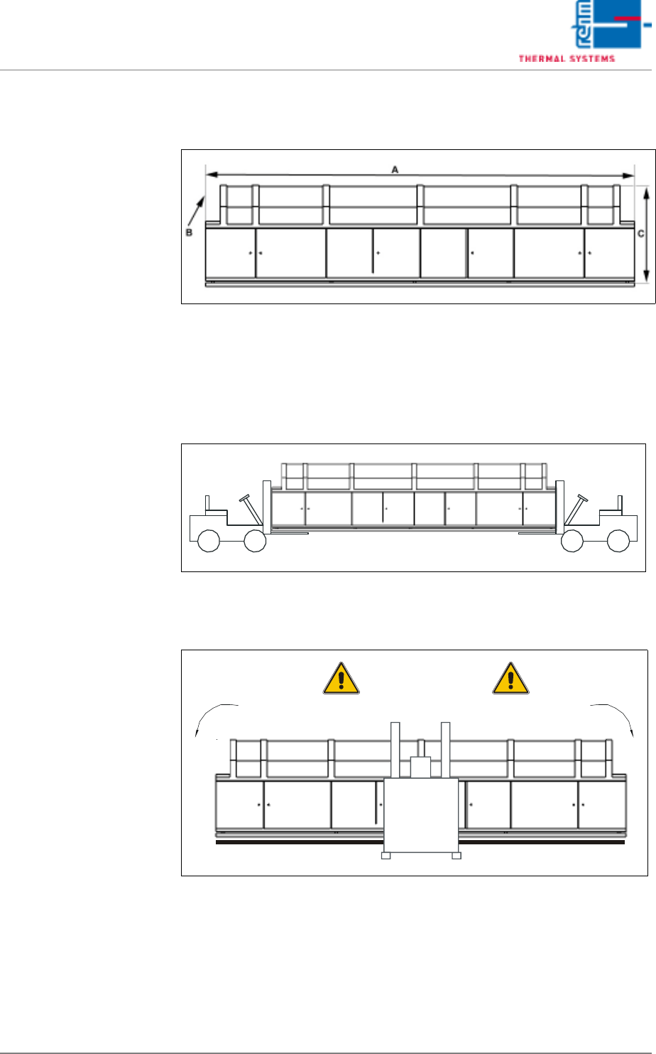
3.1.3 Transport in Basic Packaging
Dimensions
Fig. 3-1 Dimensions
Length (A), width (B) and height (C) are specified in the installation plan. Ap-
proximately 100 mm must be added to the dimensions specified in the instal-
lation plan.
Transport with Two
Forklifts or Pallet Jacks
Fig. 3-2 Transport with Two Forklifts or Pallet Jacks
Transport with One
Forklift or Pallet Jack
Fig. 3-3 Transport with One Forklift or Pallet Jack
Danger of Tilting