OperationInstruction_Vsision XP.pdf - 第90页
Page 82 V ISION XP+ V AC 5 Software 5.2 Main Window Operating Instructions V ersion 1.5 Fig. 5-1 0 Main Window A) Designations of system zones B) T emperature se tpoints for the heat ers above the conve yor are entered h…
VISION XP+ VAC Page 81
5 Software
5.2 Main Window
Operating Instructions
Version 1.5
A) Title Bar
The system designation is shown here.
B) Menu Bar
Various menus can be accessed which are required for system
operation.
C) Toolbar
The following actions can be executed by clicking the appropriate icons:
D) The loaded program is displayed here, and optionally the loaded product
as well.
Exit Visu2
Select a language
Log on a new user
Load an existing program/product
Save a program/product or create a new one
Administer the program schedule
Reload system parameters
Display protocol
Display open maintenance tasks
Display pending maintenance tasks
Start the Rehm Recorder
Jump back one window
Jump forward one window
Page 82 VISION XP+ VAC
5 Software
5.2 Main Window
Operating Instructions
Version 1.5
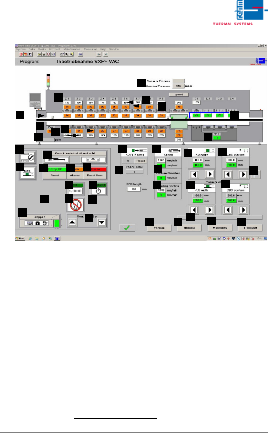
Fig. 5-10 Main Window
A) Designations of system zones
B) Temperature setpoints for the heaters above the conveyor are entered
here directly.
1
The values can be changed in the Heater window.
C) Temperature display for the heaters above the conveyor.
1
The desired tolerance can be selected with the Rel- and Rel+ parameters
in the Heating window.
D) Vacuum process
Grey display: Vacuum process is not running.
Green display: Vacuum process is running.
Chamber pressure display in mbar.
E) Temperature display for the monitoring in the process chamber.
1
The desired tolerance can be selected with the Rel- and Rel+ parameters
in the Monitoring window.
F) Temperature display for the cooling zone.
1
The desired tolerance can be selected with the Rel- and Rel+ parameters
in the Monitoring window.
Temperatures are controlled by means of temperature settings at the
cooling plant, or the external cooling system. Coolant water flow rate in-
F
E
G
H
B
A
C
D
I
J
Q
AA
Z
Y
X
W
V
U
T
S
R
P
O
N
M
L
K
AK
AI
AJ
AH
AG
AF
AB
AD
AC
AE
AM
AL
1. See also page 80, “Use of Color” and “Entering Values”.

VISION XP+ VAC Page 83
5 Software
5.2 Main Window
Operating Instructions
Version 1.5
fluences cooling efficiency. Coolant air volumetric flow can be regulated
with the frequency converter.
G) Pyrolysis display (optional))
The actual temperature of the pyrolysis is displayed here.
H) Temperature display for the heaters underneath the conveyor.
1
The desired tolerance can be selected with the Rel- and Rel+ parameters
in the Heating window.
I) Temperature setpoints for the heaters underneath the conveyor are en-
tered here directly.
1
The same values can be changed in the Heating
window.
J) Residual oxygen content display (optional).
If the display panel is blank, the analyzing unit is on display.
If the analyzing unit is (still) not ready, 999999 is displayed.
K) Cooling system intern water temperature display (only for systems with
external cooling).
1
L) Reset Emergency-Stop Button
The emergency-stop buttons snap into place when actuated. The “Reset
Emergency-Stop” button and the „Reset Alarm“ button must be activated
in order to reset the emergency stop circuit.
M) Operating Modes
The service mode is selected when maintenance, setup and repairs are
necessary. Safety devices used for monitoring whether or not the pro-
cess chambers are closed are disabled in this operating mode. Only ap-
propriate trained personnel may work with the system in the service
mode!
The automatic operating mode is used when the system is operated un-
der normal circumstances. The heating chamber and the cooling tract are
closed. The “open/close heat chamber”, “reset load” and “manual con-
veyor adjustment” functions are disabled for safety reasons.
N) Conveyor Adjustment
Switch is set to Auto: Conveyor adjustment is activated if a new setpoint
has been entered, if the setpoint deviates from the actual value and if
there are no PCBs in the system.
Switch is set to
Manual
: Conveyor adjustment is activated if the operating
mode selector switch is set to service if the scroll keys for conveyor
adjustment or the center support are activated.
In addition there are no PCB´s in the system.
If conveyor adjustment is switched from automatic to manual, the
conveyor adjustment comes to a standstill. Functioning is the same as
with manual operation. If conveyor adjustment is switched from manual to
automatic and all actual values are within the specified tolerances,
conveyor adjustment remains inactive until a new setpoint is entered.
However, if any of the actual values are not within the specified
tolerances, everything is repositioned.
O) Software button for condensate trap
The condensate trap is unlocked with this button in order to execute
1. See also page 80, “Use of Color” and “Entering Values”.