OperationInstruction_Vsision XP.pdf - 第44页
Page 36 Vision XP+ V AC 3 From T ransport to Initial Start-Up 3.3 Connections Operating Instructions V ersion 1.5 3.3.3 Electrical Connection Fig. 3-1 1 Electr ical Connec tion Refer to the circuit di agrams for con- nec…
Vision XP+ VAC Page 35
3 From Transport to Initial Start-Up
3.3 Connections
Operating Instructions
Version 1.5
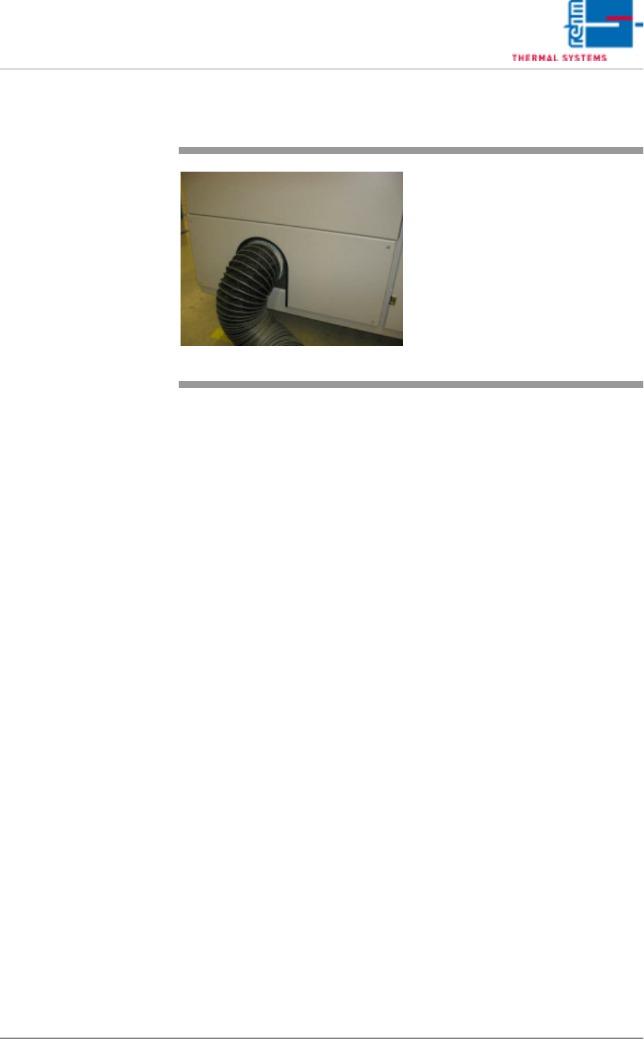
3.3.2 Exhaust Air Connection
Fig. 3-10 Exhaust air connection
VXP
The exhaust air connector pipe on
the outlet side is intended for con-
nection to the plant exhaust system.
Page 36 Vision XP+ VAC
3 From Transport to Initial Start-Up
3.3 Connections
Operating Instructions
Version 1.5
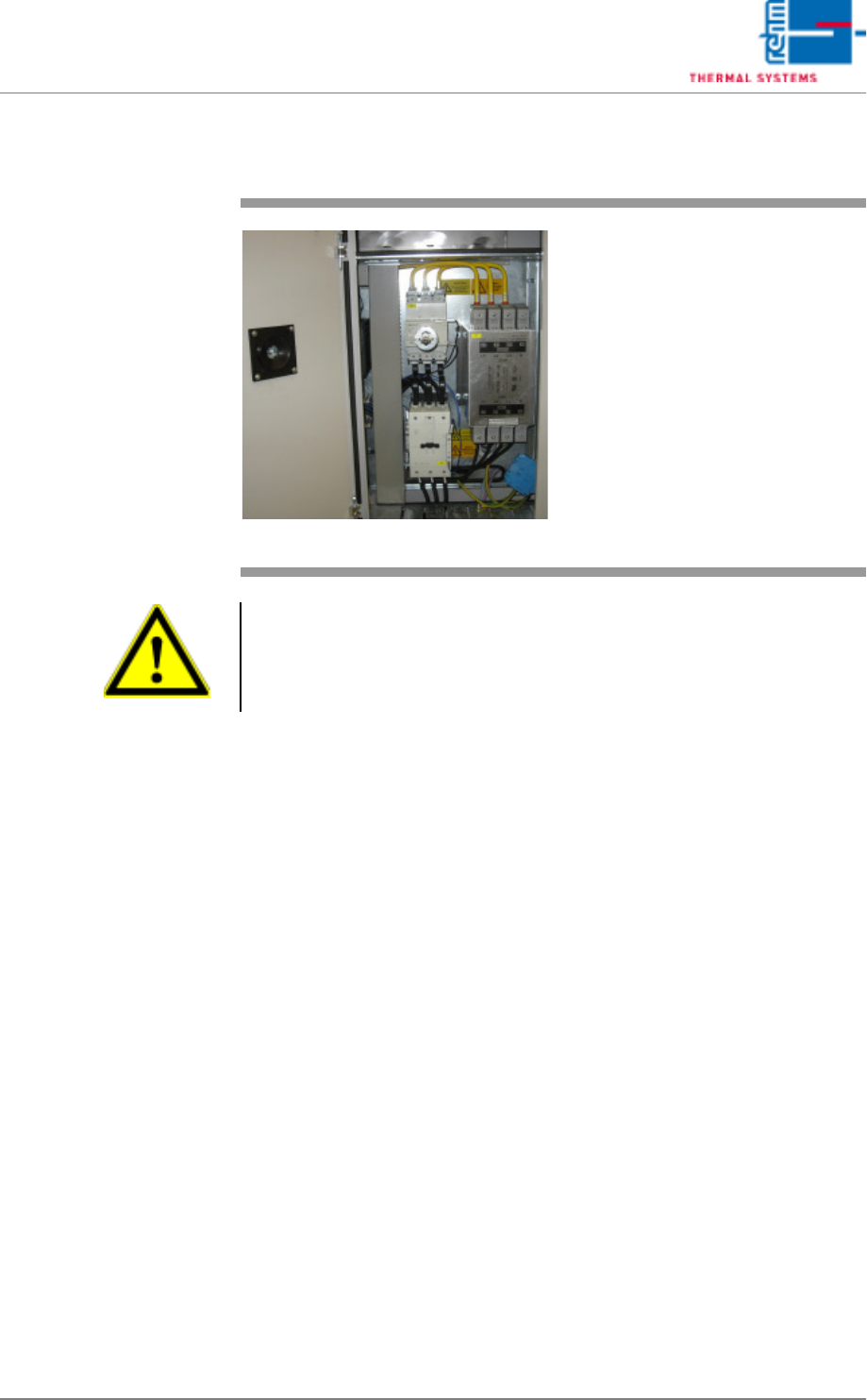
3.3.3 Electrical Connection
Fig. 3-11 Electrical Connection
Refer to the circuit diagrams for con-
nected loads. The mains connection
must be accordingly fused.
The connected line will be connect-
ed directly to the line filter.
Warning!
The system is operated with mains power. System components conduct life
endangering voltages, even when the mains switch is turned off. Improper
handling of the system may result in death or severe personal injury, as well
as substantial property damage.
Vision XP+ VAC Page 37
3 From Transport to Initial Start-Up
3.3 Connections
Operating Instructions
Version 1.5
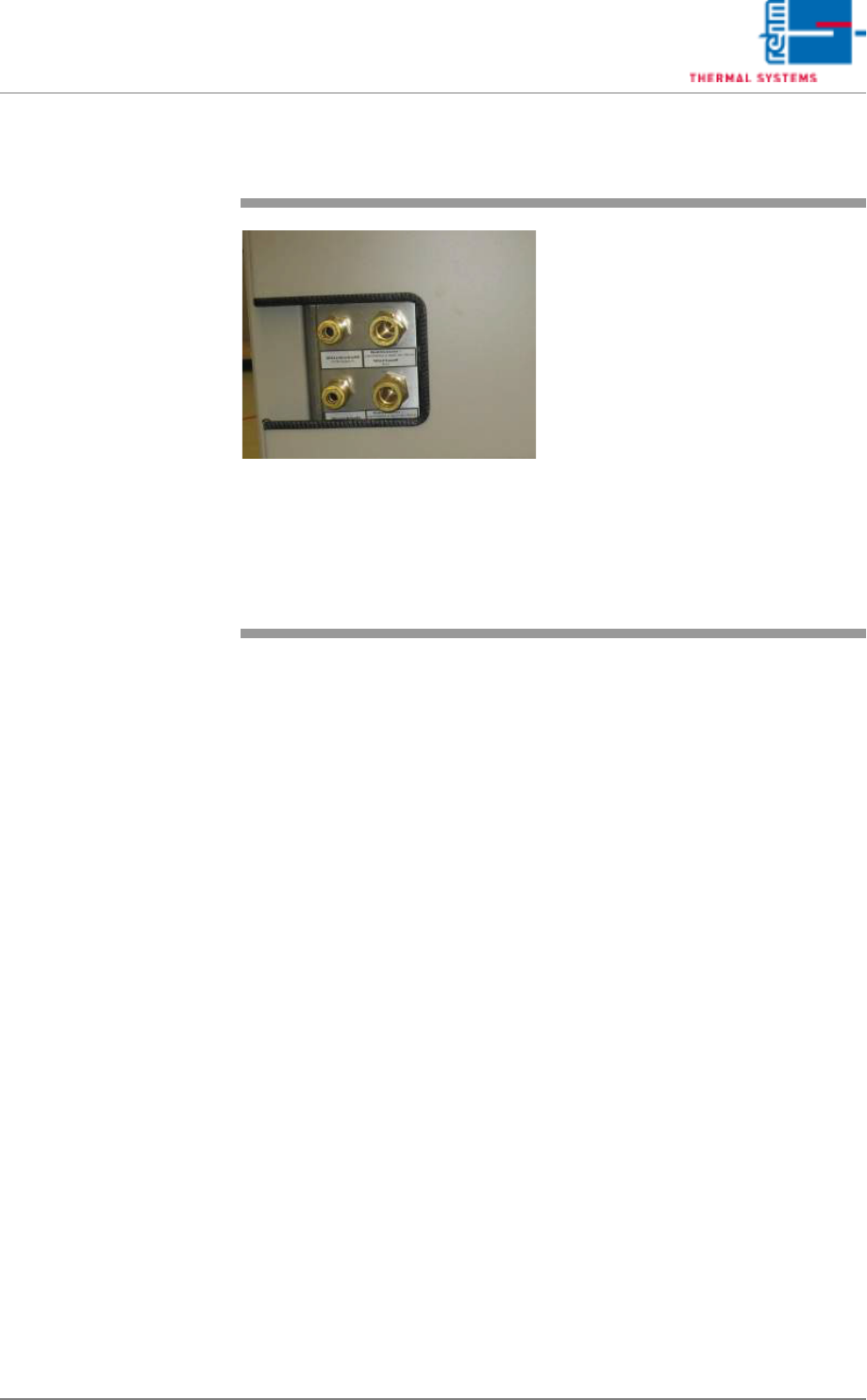
3.3.4 Water, Pressure air and Nitrogen Connections (option)
Fig. 3-12 VXP connections cooling water ex-
ternal cooling, nitrogen and com-
pressed air
Refer to the circuit diagram or the
technical data sheet for connected
loads.
Caution!
Unless absolutely necessary, do not
disconnect the nitrogen or the cool-
ant water lines when pressurized:
Danger of injury!