OperationInstruction_Vsision XP.pdf - 第46页
Page 38 Vision XP+ V AC 3 From T ransport to Initial Start-Up 3.4 Initial Start-Up Operating Instructions V ersion 1.5 3.4 Initial Sta rt-Up 3.4.1 Preparation Please check t he following points be fore configuring the sy…
Vision XP+ VAC Page 37
3 From Transport to Initial Start-Up
3.3 Connections
Operating Instructions
Version 1.5
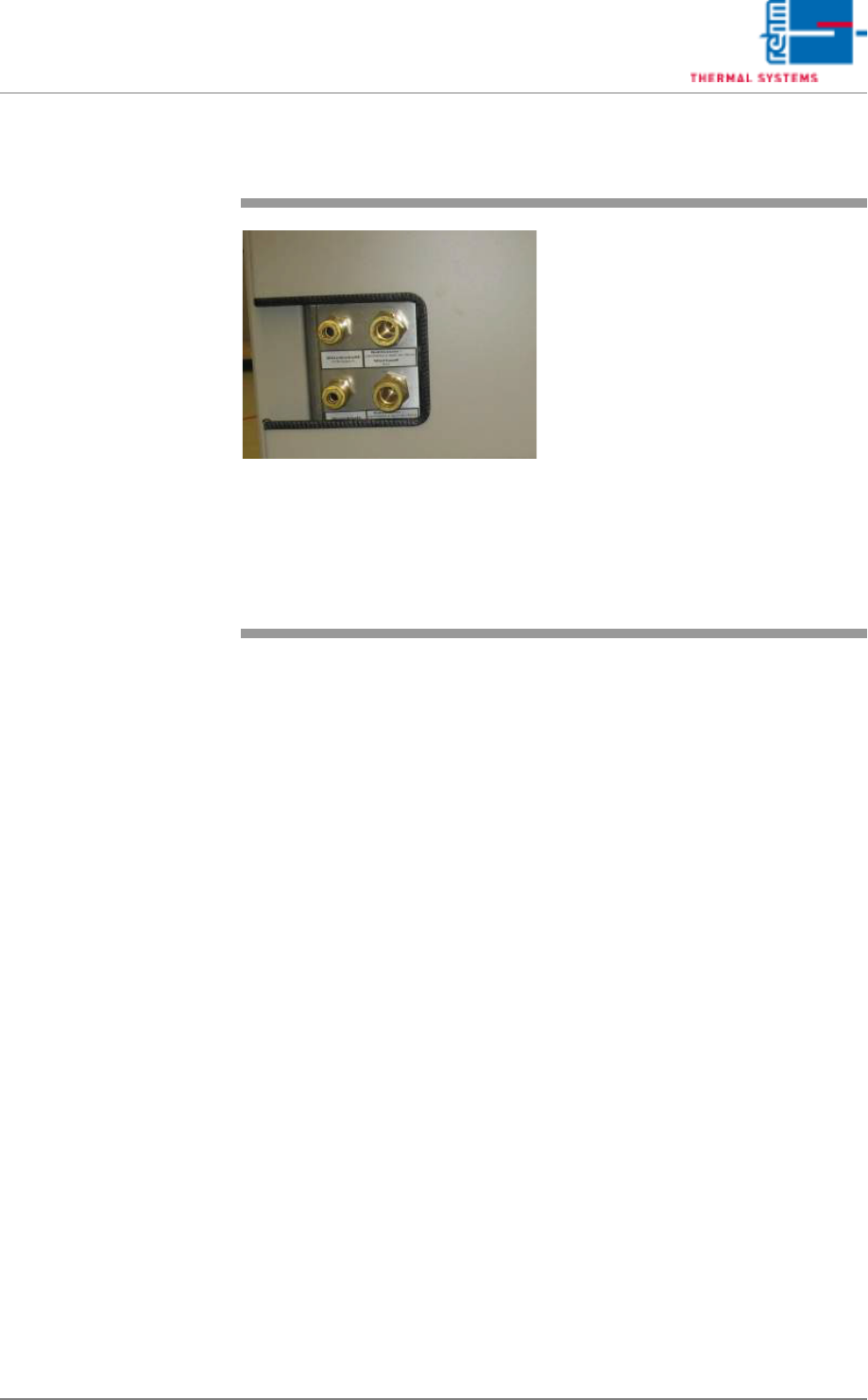
3.3.4 Water, Pressure air and Nitrogen Connections (option)
Fig. 3-12 VXP connections cooling water ex-
ternal cooling, nitrogen and com-
pressed air
Refer to the circuit diagram or the
technical data sheet for connected
loads.
Caution!
Unless absolutely necessary, do not
disconnect the nitrogen or the cool-
ant water lines when pressurized:
Danger of injury!

Page 38 Vision XP+ VAC
3 From Transport to Initial Start-Up
3.4 Initial Start-Up
Operating Instructions
Version 1.5
3.4 Initial Start-Up
3.4.1 Preparation
Please check the following points before configuring the system:
1. The system has been set up in accordance with the setup instructions.
2. Electrical supply power is in compliance with the specifications included
in the operating instructions and the “Technical Data Sheet”.
3. Make sure that the system has been connected to electrical power, com-
pressed air, nitrogen and coolant water.
4. Make sure that the system has been connected to the exhaust air sys-
tem.
5. Make sure that all required fluids (coolant water, chain oil) have been
filled up.
6. Conduct a visual inspection of the system. It is especially important to
ensure that there are no obstacles within the conveyor system’s travel
path.
7. All process chambers and hoods must be closed.
8. Make sure that all emergency-stop buttons are deactivated.

Vision XP+ VAC Page 39
3 From Transport to Initial Start-Up
3.4 Initial Start-Up
Operating Instructions
Version 1.5
3.4.2 Switching the System On
1. Turn the system on with the mains switch.
2. If an uninterruptible power supply has been installed, it is turned on with
the On/Off button.
3. The operating system is started. The login window may appear at the
monitor after approximately 1 minute.
4. Type Administrator into the “User Name” field and AdmV8 into the
“Password” field, and acknowledge by clicking the OK button.
5. “Visu2 is started automatically. The password prompt window appears.
6. When using the software for the first time, enter Administrator to the
“Name” field and AdmV8 to the “Password” field. After Visu2 has been
initialized, change the administrator password (see chapter 5.3.2
Changing a Password, on page 91) and enter a new user (see chapter
5.3.3 User Administration, on page 92).
7. Make sure that the loaded program is the right program for the product
to be manufactured. If not, load an appropriate program (see chapter
5.4.1 Load Program, on page 100). If no program is available, adjust
system settings appropriately and save them using a new program
name.
8. Start the PCB conveyor by clicking the Drive On/Off icon.
9. Turn on the heaters by clicking the Heat On/Off icon.
10. After about 30 minutes, the green signal lamp lights up in order to indi-
cate that the system is ready for operation.
Note!
The normal operating state upon power up N2 systems is when the traffic
signal is red. In systems without N2 the traffic lights are only orange.