OperationInstruction_Vsision XP.pdf - 第80页
Page 72 Vision XP+ V AC 4 Equipment 4.9 Nitrogen (optional) Operating Instructions V ersion 1.5 4.9.2 Scavenging Circuit • When nitr ogen supply i s started up, the s cavenging circuit is a ctivated for a period of appro…
Vision XP+ VAC Page 71
4 Equipment
4.9 Nitrogen (optional)
Operating Instructions
Version 1.5
4.9 Nitrogen (optional)
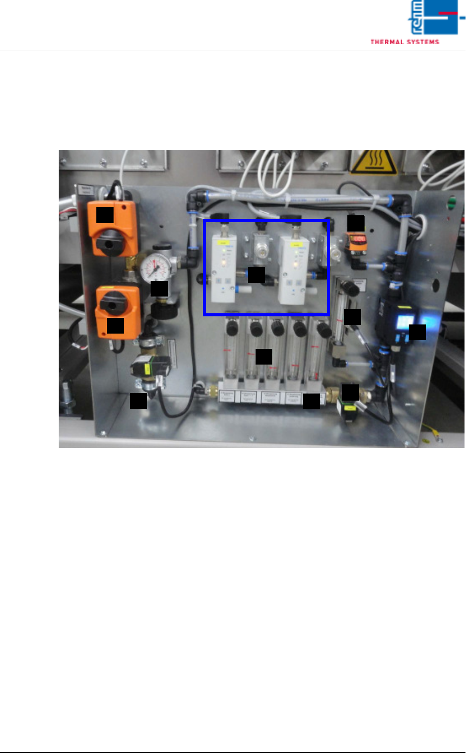
4.9.1 Layout of the Compressed Air and Nitrogen Unit
Fig. 4-54 Compressed Air and Nitrogen Unit
A) Pressure sensor
B) Nitrogen control
C) Isolation purge valve (pressure meter)
D) Flow meter / Pyrolysis with monitoring for venturi tube
E) Nitrogen switching (motor actuator)
F) Pressure gauge (behind the motor actuator)
G) Compressed air switching (motor actuator)
H) Nitrogen feed to process chamber (flow meter)
I) N2/O2 switch over valve
J) Purge valve process chamber
K) N2 usage indicator
F
A
E
H
G
K
D
J
C
B
I
Page 72 Vision XP+ VAC
4 Equipment
4.9 Nitrogen (optional)
Operating Instructions
Version 1.5
4.9.2 Scavenging Circuit
• When nitrogen supply is started up, the scavenging circuit is activated for
a period of approximately 45 minutes.
The purge valves (J) and the flow meter are opened for the specified period
of time. Nitrogen is blown into peak zones 1 and 3 and into lining. Also in the
nozzle holder for the VXP+
4.9.3 Distribution
• When the inert gas function is activated, nitrogen is fed to the various in-
jection points by a purge valve (J).
• Pressure is indicated at the pressure gauge (C).
• Consumption per hour is indicated by the flow meter (H).
• An alarm message is generated if the lower limit value selected for the
pressure sensor (A) is fallen short of.
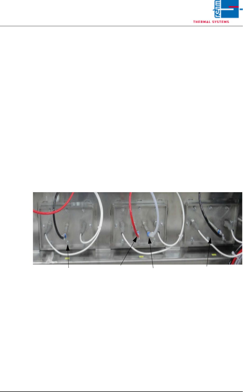
4.9.4 Connections of the nitrogen regulation
Fig. 4-55 N2 regulation
With the option „Nitrogen regulation“ the basic valve is connected in Peak
1+3. In Peak 2 the control valve is connected to the first connecting piece
and the analysis lead to the second one.
Peak 3
Peak 2
Peak 1
Analysis
Control valve
Basic valve
Basic valve
Vision XP+ VAC Page 73
4 Equipment
4.9 Nitrogen (optional)
Operating Instructions
Version 1.5
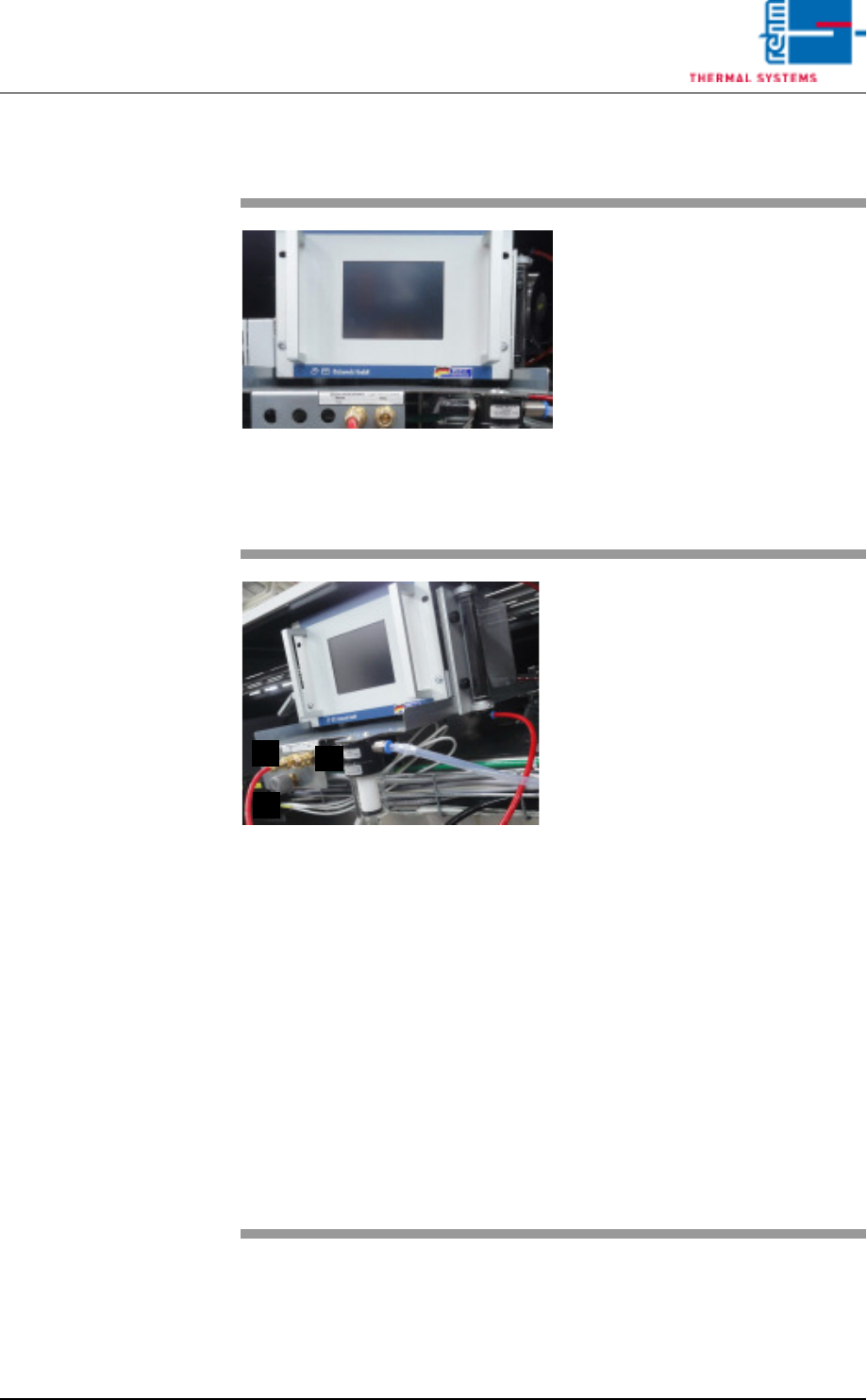
4.9.5 Residual Oxygen Measurement (optional)
Fig. 4-56 Residual Oxygen Measuring In-
strument
Residual oxygen content within the
system is checked in the event of:
– Initial start-up
– Process monitoring
– Deterioration of soldering results
– Relocation of the system
Residual oxygen measuring device
is required for measurement. Mea-
surement device as well as mea-
surement connections are located
at the system rear side.
Fig. 4-57 Residual Oxygen Measuring In-
strument: Connections
The measuring points mains (A) und
peak (B) are available as standard.
Optionally, the measuring points
can be extended to pre-heating,
centre and cooling section.
The quality of the nitrogen supply to
the system can be checked on the
basis of the measuring point net-
work.
Proceeding:
Open adjusting valve C by one turn
(nitrogen escapes at T – piece of the
measuring point mains).
Plug in the measurement connec-
tion at the mains.
Measured residual oxygen content
is displayed at the monitor screen,
as well as at the meter. A limit value
with alarm signal can be specified
by the user.
For detailed information regarding
use refer to the included Operating
Instructions for the Measuring In-
strument.
B
A
C