OperationInstruction_Vsision XP.pdf - 第144页
Page 136 V ISION XP+ V AC 5 Software 5.6 The Protocol Menu Operating Instructions V ersion 1.5 5.6.1 Protocol Definition Fig. 5-6 1 Prot ocol Defini tion Selected protoc ol data are display ed. In addition to this, exist…
VISION XP+ VAC Page 135
5 Software
5.6 The Protocol Menu
Operating Instructions
Version 1.5
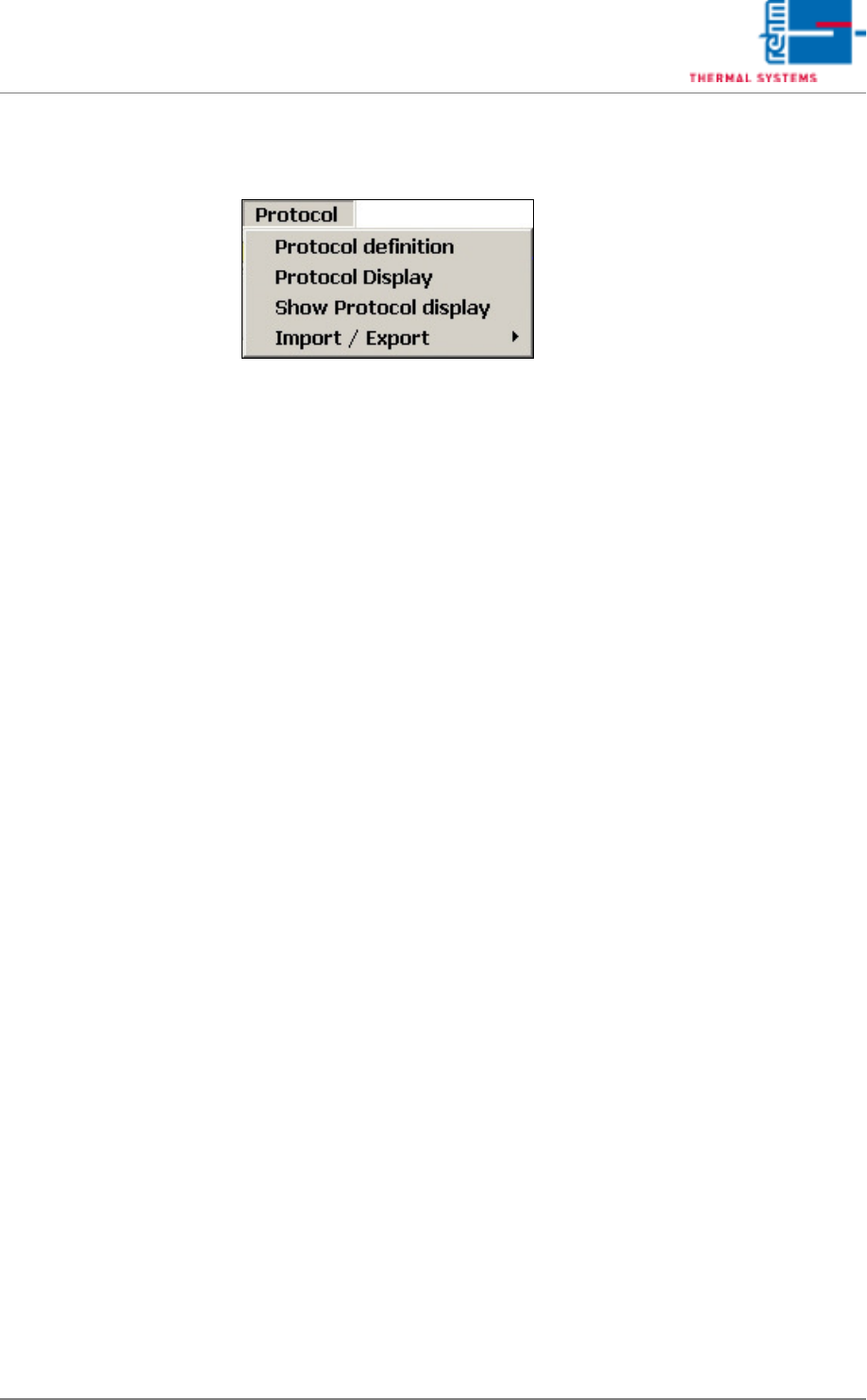
5.6 The Protocol Menu
All changes of status with regard to digital inputs and outputs, setpoints,
actual values, alarm values and defined program changes are documented
in the protocol.
A protocol is always generated when the switching status of a digital input or
output is changed. For example, this is the case when a button is clicked, or
when an error occurs which triggers an alarm.
Page 136 VISION XP+ VAC
5 Software
5.6 The Protocol Menu
Operating Instructions
Version 1.5
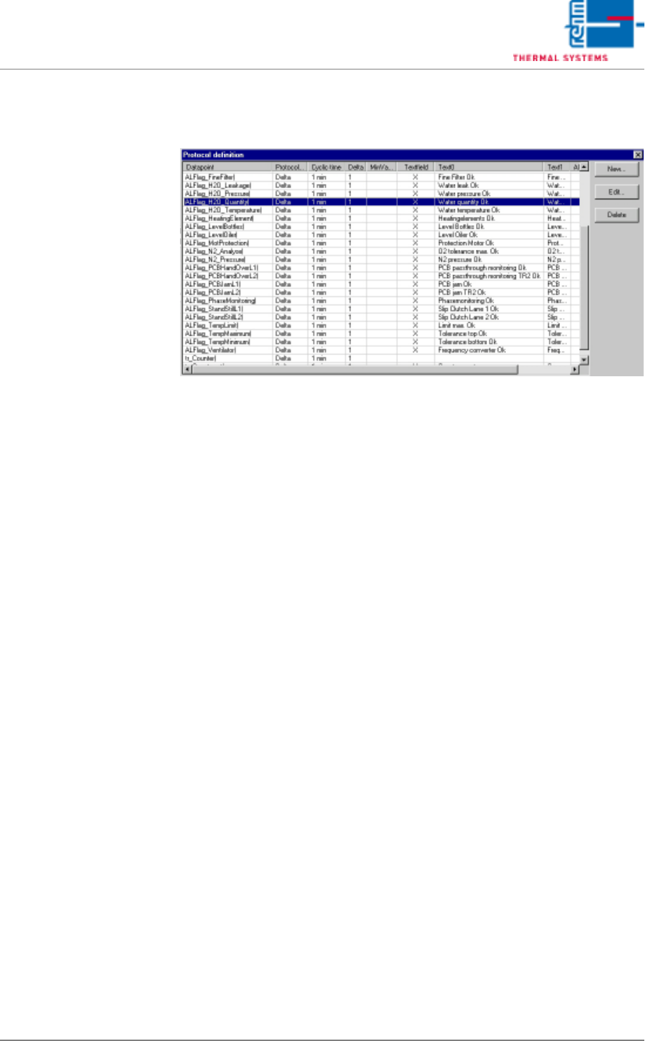
5.6.1 Protocol Definition
Fig. 5-61 Protocol Definition
Selected protocol data are displayed.
In addition to this, existing data points can be edited here, and new ones can
be entered for inclusion in the protocol. The New and Edit buttons are used
to this end.
Protocol generation is triggered if an event occurs. Statuses are appended
to the events. Related statuses are also logged when an event occurs. You
can trigger a protocol yourself as well.
Example
Event: temperature alarm
Related statuses: temperature zone 1, temperature zone 2, temperature
zone 3. When a temperature alarm is pending, temperatures in zones 1, 2
and 3 are logged as well.
VISION XP+ VAC Page 137
5 Software
5.6 The Protocol Menu
Operating Instructions
Version 1.5
New Protocol Definition
Edit Protocol Definition
Fig. 5-62 Edit Protocol Definition (events window)
Events Window
A) Querying Cycle
An interval is entered at which checking takes place to determine
whether or not an event has occurred.
Caution!
Short intervals for many different events may overload the computer.
B) Cyclical Protocol
The data point is also entered to the protocol for each querying cycle.
C) Tolerance protocol (the event only occurs if the tolerance range is
exceeded or fallen short of).
The user is able to define a special tolerance range for reporting
purposes. The upper and lower tolerances are specified relative to the
setpoint with Rel+ and Rel-. If the data point lies within the specified
tolerance range, it is logged as a positive result and is highlighted green.
If it does not lie within the specified tolerance range, it is logged as a
negative result and is highlighted red.
D) Alarm Range Protocol
The alarm range protocol has the same function as the tolerance proto-
col. However, setpoint parameters Rel+ and Rel- are taken from the
control channel, and depend upon the currently loaded program. Only
those data points can be selected which have been defined as control
channels.
E) Delta Protocol
An event occurs when the data point changes by at least the value which
has been entered to the delta parameter field, and is larger than the value
which has been entered to the minimum value parameter field.
F) Available Statuses
All defined, and thus possible statuses are listed here.
D
C
B
A
H
GF
E