OperationInstruction_Vsision XP.pdf - 第129页
V ISION XP+ V AC Page 121 5 Software 5.5 The Masks Menu Operating Instructions V ersion 1.5 Fig. 5-4 9 N2 Operating Mode (exc erpt) M) Di splay of oxyge n meter operating state Po ss ib le st at es Of f: Th e ox yg en m …

Page 120 VISION XP+ VAC
5 Software
5.5 The Masks Menu
Operating Instructions
Version 1.5
ed. It remains open until the system is once again empty for the first time
after the purging phase. Thereafter, it is always open when the system is
loaded. This function can be deactivated here. The valve is always open
in this case.
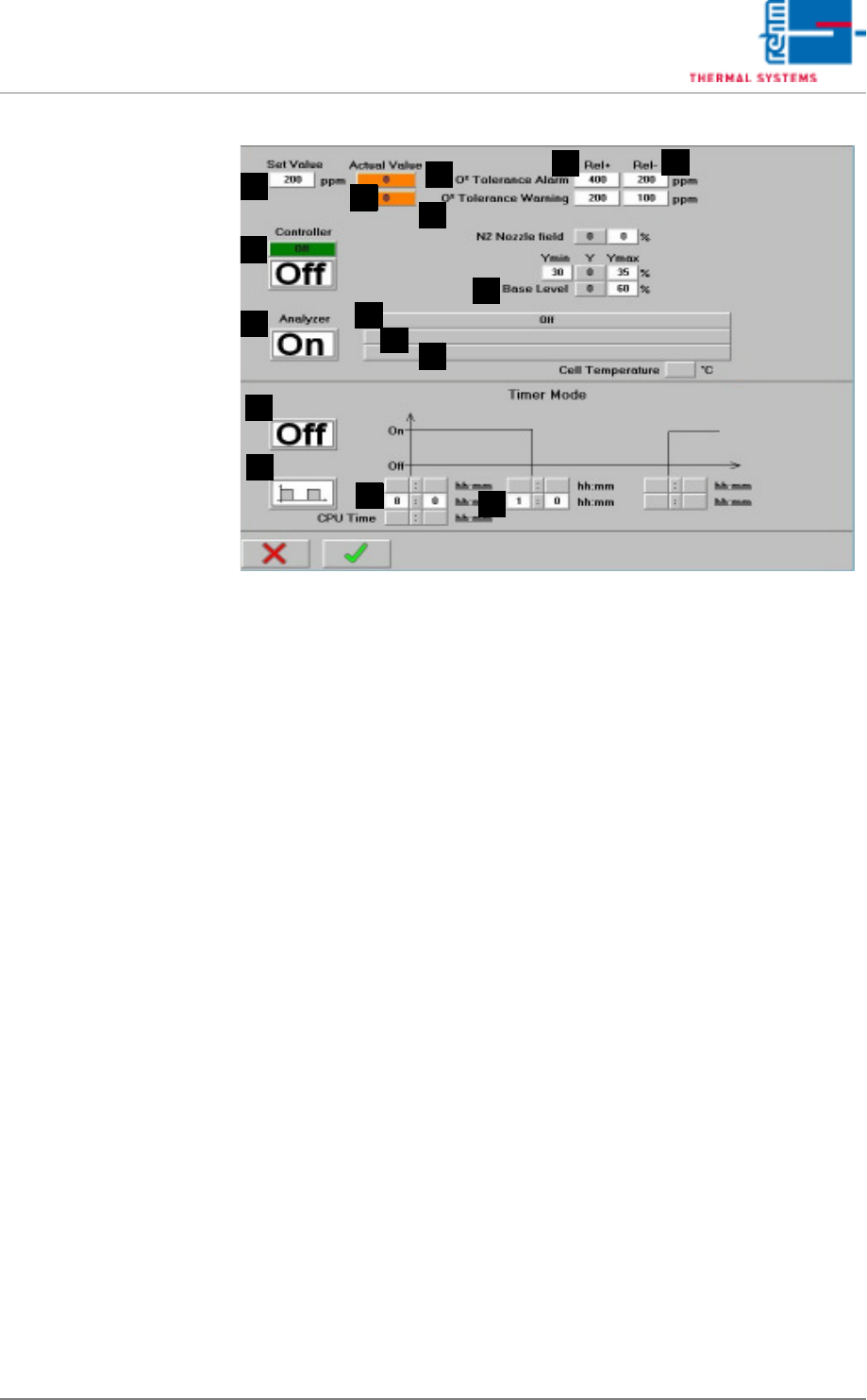
D) Set Value
Entry field for the residual oxygen setpoint.
E) Actual Value
Residual oxygen content display. If the residual oxygen meter does not
yet ready the display shows 999999.
F) Rel+
The relative upper tolerance limit can be selected here, relative to the
setpoint.
G) Rel-
The relative lower tolerance limit can be selected here, relative to the set-
point.
H) O2 tolerance violation
If the tolerance is exceeded or fallen short of, the “O2 tolerance” alarm is
triggered. No further work can be performed. In the flushing phase or af-
ter the program change until the set value is achieved for the first time,
no buzzer sounds with this alarm.
I) O2 tolerance warning (option)
This is a preliminary warning which precedes the “O2 tolerance” alarm. A
horn sounds if the tolerance is exceeded or fallen short of. Work can nev-
ertheless be continued.
J) Control mode
The control mode can be activated by entering different values for Y-min
and Y-max, and setting the Control mode button to ON.
Y-min = min. opening for N2 control valve
Y-max = max. opening for N2 control valve
Y = current setting is displayed.
K) Base Level
The valve's manipulated variable is set here for the basic level.
L) Oxygen meter on/off
The residual oxygen meter can be switched on and off here.
VISION XP+ VAC Page 121
5 Software
5.5 The Masks Menu
Operating Instructions
Version 1.5
Fig. 5-49 N2 Operating Mode (excerpt)
M) Display of oxygen meter operating state
Possible states
Off: The oxygen meter is switched off.
Cycle mode active: oxygen meter on
timer mode on
cycle mode
The oxygen meter is performing a measurement.
Cycle mode inactive: oxygen meter on
timer mode on
cycle mode
The oxygen meter is pausing between measurement.
Clock time mode active: oxygen meter on
timer mode on
clock time mode
The oxygen meter is performing a measurement.
Clock time mode inactive: oxygen meter on
timer mode on
cycle mode
The oxygen meter is pausing between measurement.
Continuous operation: oxygen meter on
timer mode off
Continuous measurement is performed with the residual oxygen meter.
Measurement after opening active: oxygen meter on
timer mode on
cycle mode or clock time mode
The process chamber has been opened and then closed again.
Measurement is thus started for a fixed period of 1 hour.
F
Q
J
G
K
R
T
S
O
P
N
E
M
L
H
I

Page 122 VISION XP+ VAC
5 Software
5.5 The Masks Menu
Operating Instructions
Version 1.5
Continuous operation via controller: I = oxygen meter off
or I = oxygen meter on
and M = timer mode on
If the controller is activated and the oxygen meter has not been set to
continuous operation, it is switched on automatically. However, it is
advisable to activate continuous operation manually as well.
N) Display of oxygen meter controls
Pump off: measurement with oxygen meter inactive
Pump low: measurement with oxygen meter active, pump performance
set to low
Pump high: with B & R controllers only, pump set to high
Active during the purging phase or nitrogen regulation.
O) Display of oxygen meter error messages (with B & R controllers only)
No error: Residual oxygen meter is functioning normally
Transmission error: faulty connection, or incorrect configuration of
the RS 232 connection
System error: general oxygen meter error message
Defective thermocouple: defective thermocouple in the oxygen meter
Temperature too low: detector has not reached the setpoint
temperature
Detector resistance too high: resistance at the measuring detector is
too high
Detector voltage > 500 mV: measuring detector voltage is greater
^ than 500 mV
P) Timer mode
The timer mode can be activated here for the residual oxygen meter, if it
has been activated.
Q) Cycle mode / Clock time mode
R) Start-up time
If the clock time mode is selected, the oxygen meter is switched on at
the specified time. If the cycle mode is selected, the entire cycle is en-
tered here.
S) Shutdown time
If the clock time mode is selected, shutdown takes place at this point in
time.
If the cycle mode is selected, duration of the measurement is entered
here.
The duration of the measurement begins when the overall cycle is start-
ed.
Fig. 5-50 Cycle mode
If the cycle mode is activated, the oxygen meter
is switched on and off at specified time inter-
vals.
Fig. 5-51 Clock time mode
If the clock time mode is activated, the oxygen
meter is switched on at the time specified, and
is switched off at the time specified.