OperationInstruction_Vsision XP.pdf - 第42页
Page 34 Vision XP+ V AC 3 From T ransport to Initial Start-Up 3.3 Connections Operating Instructions V ersion 1.5 3.3 Connectio ns 3.3.1 Connection Locations VXP+ V AC Fig. 3-9 Electrica l, Comp ressed Air and Nitroge n …
Vision XP+ VAC Page 33
3 From Transport to Initial Start-Up
3.2 Setup Instructions
Operating Instructions
Version 1.5
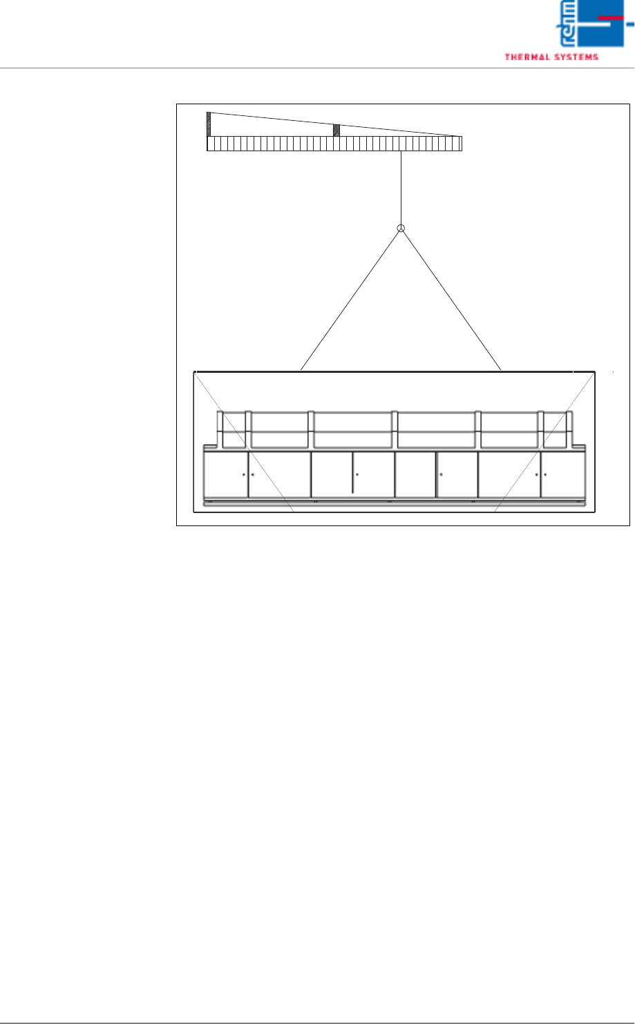
Transport in Wooden
Crate with Crane
Fig. 3-8 Transport in Wooden Crate with Crane
3.2 Setup Instructions
The installation place has to be dust-free and dry. The permissible ambient
temperature is +5°C until +35°C.
1. Turn all inside leveling feet in until the system is supported exclusively
by the four leveling feet at the corners.
2. Adjust the leveling feet such that the conveyor is at the same height as
the conveyor system of the upstream machine.
3. Make sure that the distance from the system inlet and the system outlet
to adjacent equipment is at least 1 cm.
4. Precisely level the system, both widthwise and lengthwise, with the help
of a level.
5. Turn the inside leveling feet out until the machine base no longer sags
(visual inspection).
6. Secure the leveling feet with lock nuts.
7. Install the components which have been removed for transport.
8. Connect all supply lines.
Page 34 Vision XP+ VAC
3 From Transport to Initial Start-Up
3.3 Connections
Operating Instructions
Version 1.5
3.3 Connections
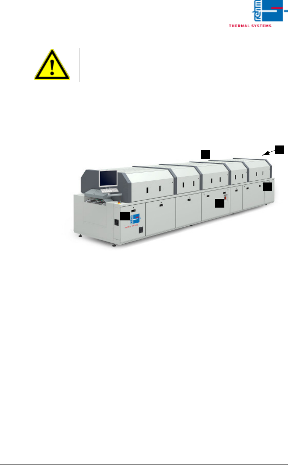
3.3.1 Connection Locations VXP+ VAC
Fig. 3-9 Electrical, Compressed Air and Nitrogen Connection Locations
A) Exhaust air connection
B) Inlet interface connection (internal)
C) Power supply connection
D) Outlet interface connection (internal)
E) Nitrogen and compressed air connections (underneath the outlet area)
Attention!
Electrical power may only be connected by personnel who have been ap-
propriately trained and certified.
A
D
B
C
E
Vision XP+ VAC Page 35
3 From Transport to Initial Start-Up
3.3 Connections
Operating Instructions
Version 1.5
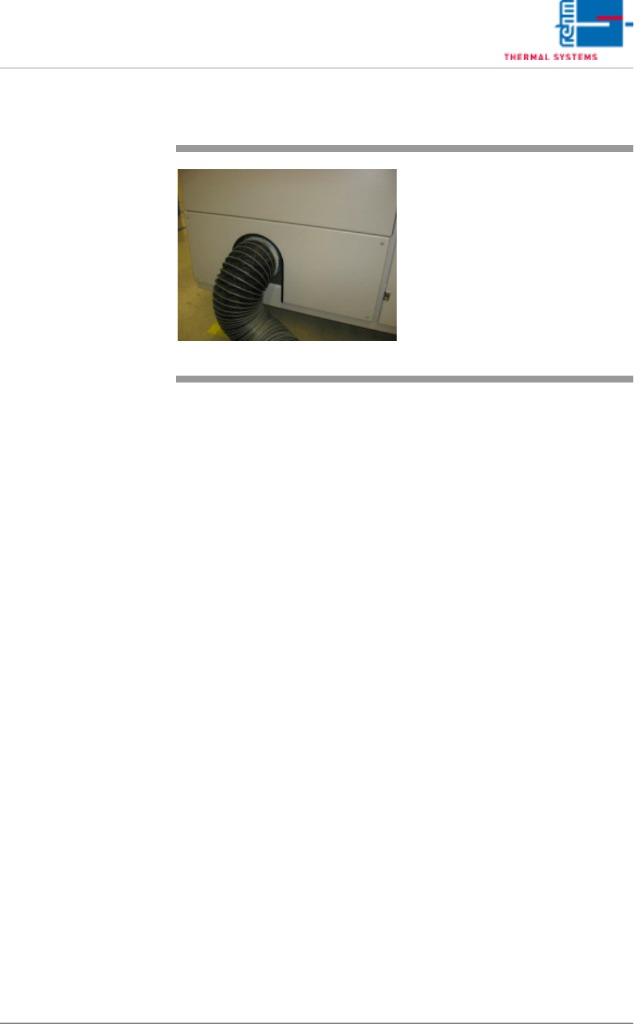
3.3.2 Exhaust Air Connection
Fig. 3-10 Exhaust air connection
VXP
The exhaust air connector pipe on
the outlet side is intended for con-
nection to the plant exhaust system.