OperationInstruction_Vsision XP.pdf - 第133页
V ISION XP+ V AC Page 125 5 Software 5.5 The Masks Menu Operating Instructions V ersion 1.5 5.5.12 F an Monitoring (optional) Fig. 5-5 4 Fa n Monitoring The fan mo nitoring function indicat es whether or not a ll of the …
Page 124 VISION XP+ VAC
5 Software
5.5 The Masks Menu
Operating Instructions
Version 1.5
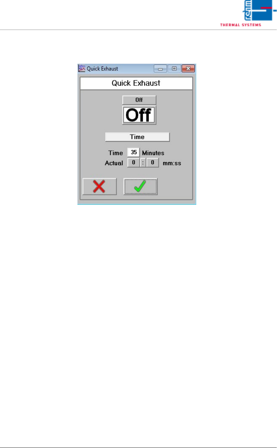
5.5.11 Quick Exhaust (optional)
Fig. 5-53 Quick Exhaust
Quick exhaust is for quick cooling down at maintenance works or for
program change – bonding profile.
Quick exhaust can be controlled here over software. With the software on/
off switch the function is switched on or off.
Temperature/Time
With the software switch the operating mode of the quick exhaust can be
selected. In the mode Temperature there is control over temperature and in
the mode Time over a virtual time switch.
Timer operation (mode Time)
After the quick exhaust is switched from Off to On, it is active for the set
time and afterwards switches off again automatically. The cycle is restarted
through re-switching on.
Temperature operation (Mode Temperature)
If the quick exhaust is switched on, the heating zones are monitored
separately with program change. If one of the heating zones exceeds the
admissible tolerance upper limit, the quick cooling down is activated.
VISION XP+ VAC Page 125
5 Software
5.5 The Masks Menu
Operating Instructions
Version 1.5
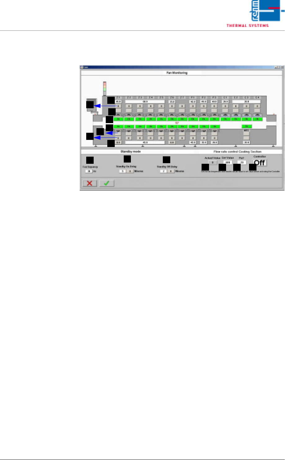
5.5.12 Fan Monitoring (optional)
Fig. 5-54 Fan Monitoring
The fan monitoring function indicates whether or not all of the fans are
running at the correct speed in RPM.
A) Frequency setpoint (entry field)
The frequency setpoint for the frequency converter is entered here. A sin-
gle field makes reference to one or more fans.
B) Frequency setpoint (display value)
The frequency setpoint is displayed for each individual fan.
If the parameters have been configured correctly, the respective set-
points in A and B must coincide.
C) Actual frequency value (for B&R controller only)
The actual frequency value is displayed for each individual fan. The ac-
tual value must coincide with the respective setpoint. The value is dis-
played in green if it lies within a tolerance of +2 / -5 Hz. It is displayed in
red if it is out of tolerance. The fan is malfunctioning.
D) Fan status (for S7 controller only)
Indication is displayed here for each individual fan as to whether or not
speed in RPM is within the permissible, internally calculated tolerance. If
everything is OK, the field is green and “OK” appears at the display. If the
tolerance is violated, the field is red and “Error” appears at the display.
The fan is malfunctioning.
E) Fan frequency
Entry of fan frequency in Hz for the standby mode.
F) Standby On-Delay
Entry for delay time until the standby mode is activated.
G) Standby Off-Delay
Entry for delay time until the standby mode is deactivated.
A
D
C
B
A
D
C
B
G
F
E
H
I
K
J
Page 126 VISION XP+ VAC
5 Software
5.5 The Masks Menu
Operating Instructions
Version 1.5
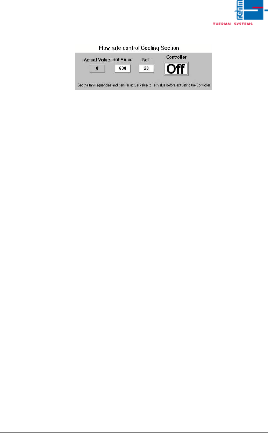
The volume flow control
(option)
Fig. 5-55 Fan monitoring - volume flow control
The volume flow control regulates the cooling section fan frequencies in or-
der to maintain the specified volume flow.
If the volume flow exceeds tolerances “” on page 90) the message “Change
filter F9" is displayed on the main screen and the alarm “Volume flow control
cooling section” triggers.
If the fans in the individual zones are controlled by different frequency con-
verters, the different fan frequency settings are maintained also in normal
operation.
e.g. set C2 = 20.0 Hz,
C3 and C4 = 25.0 Hz.
In controlled operation, the 5 Hz difference between C2 and C3 / C4 is main-
tained.
Commissioning:
Press the ON/OFF key to deactivate volume flow control. The fan speed now
has a fixed value and volume flow is established. Take the displayed actual
value as the new target value. Now activate volume flow control again by
pressing the ON/OFF key. Permissible volume flow tolerances may be en-
tered in the “Rel-“ field. Finish and save the program.
H) Actual value
Current differential pressure, volume flow.
I) Set-point
Volume flow Set-point value.
J) Controlled operation ON/OFF
Activating/deactivating volume flow control.
K) Rel-
Permitted volume flow tolerance.