OperationInstruction_Vsision XP.pdf - 第70页
Page 62 Vision XP+ V AC 4 Equipment 4.4 The Process Chamber Operating Instructions V ersion 1.5 4.4.1 1 Quick cooling down SSP (option) 4.4.12 Q uick cooling SSP+ Fig. 4-3 5 Quick cooling d own SSP Fig. 4-3 6 Quick cooli…
Vision XP+ VAC Page 61
4 Equipment
4.4 The Process Chamber
Operating Instructions
Version 1.5
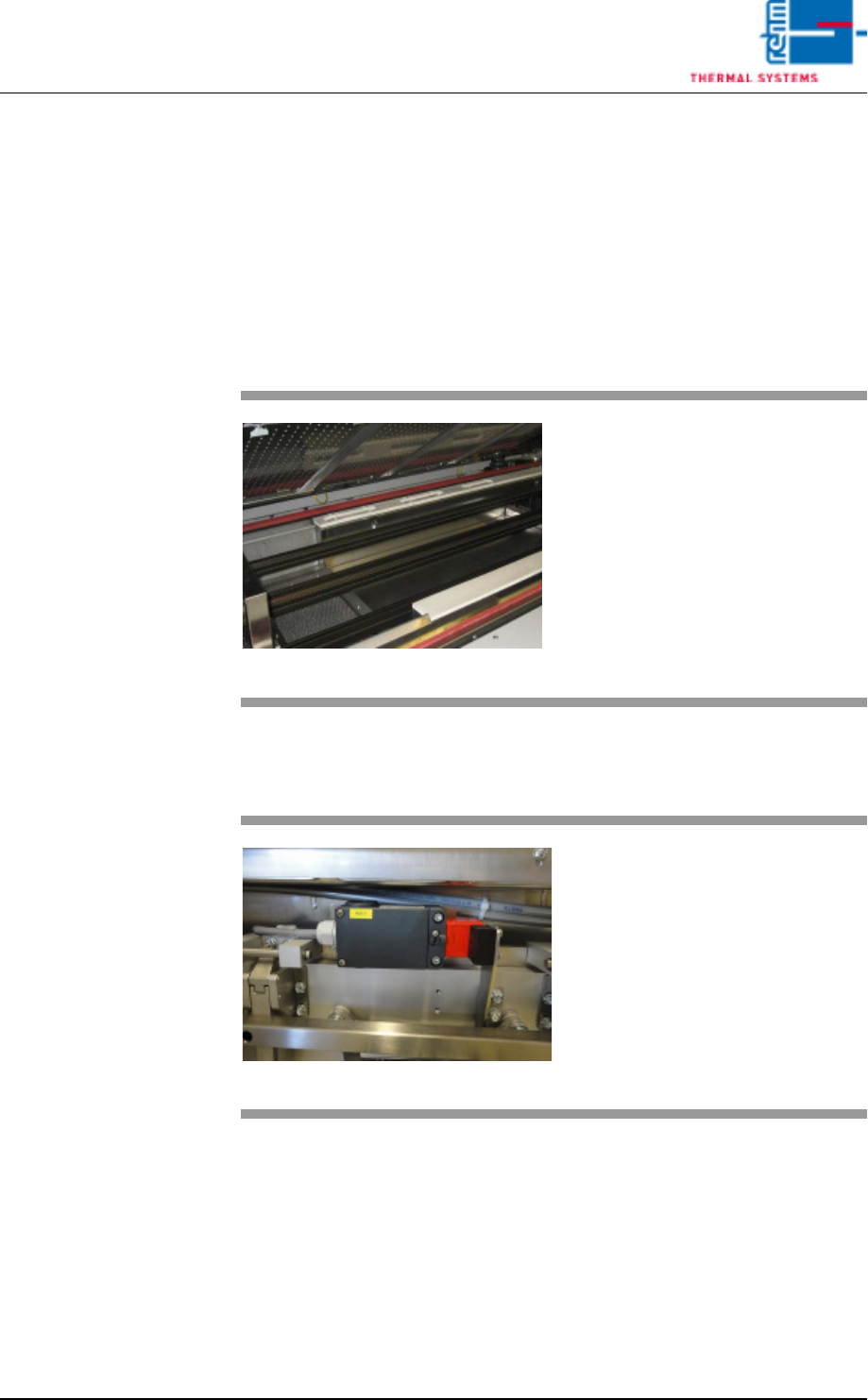
4.4.9 The Cooling Tract
Note!
The transmission zone is located at the transition between the peak zone
and the cooling zone. A heating module is installed to the first cooling zone
which can be activated if necessary. The cooling gradient can be adjusted in
a highly flexible manner by means of temperature an frequency through the
use of this heating module. This infinitely adjustable influence on the cooling
gradient is necessary in order to assure stressless cooling for sensitive com-
ponents.
4.4.10 Safety switch cooling section VXP+
Fig. 4-33 The Cooling Tract
The PCBs are cooled down with the
help of nozzle sheets, which are lo-
cated above the conveyor system.
The required gas recirculation is
generated over blowers located at
the rear side of the system.
Fig. 4-34 Safety switch cooling section VXP+
As soon as the cooling section is
opened, the additional safety switch
in the cooling section is activated.
The fans of the cooling section are
switched off for safety-related pur-
poses.
Page 62 Vision XP+ VAC
4 Equipment
4.4 The Process Chamber
Operating Instructions
Version 1.5
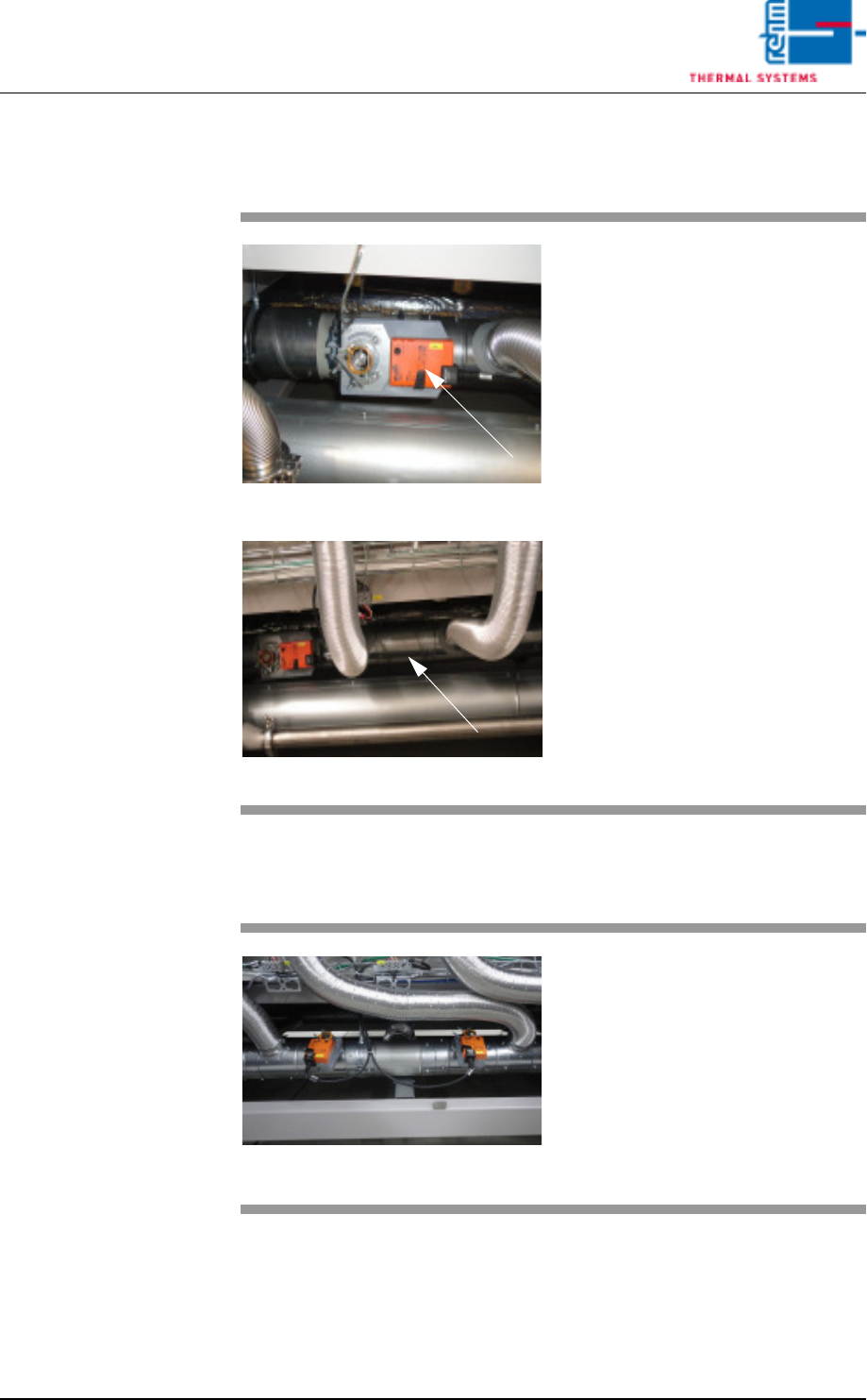
4.4.11 Quick cooling down SSP (option)
4.4.12 Quick cooling SSP+
Fig. 4-35 Quick cooling down SSP
Fig. 4-36 Quick cooling down SSP
For the option cooling down an ad-
ditional suction pipe as well as an
electric shut-off valve are used in
the rear part of the machine below
the heating.
This option „Quick cooling down“ is
used for quick cooling down of too
hot zones after program change.
Fig. 4-37 Quick cooling SSP+
The first throttle actuator is for cool-
ing the preheating zones to facilitate
more effective zone separation.
The second throttle actuator is in-
stalled for quick cooling of peak
zones.
Vision XP+ VAC Page 63
4 Equipment
4.4 The Process Chamber
Operating Instructions
Version 1.5
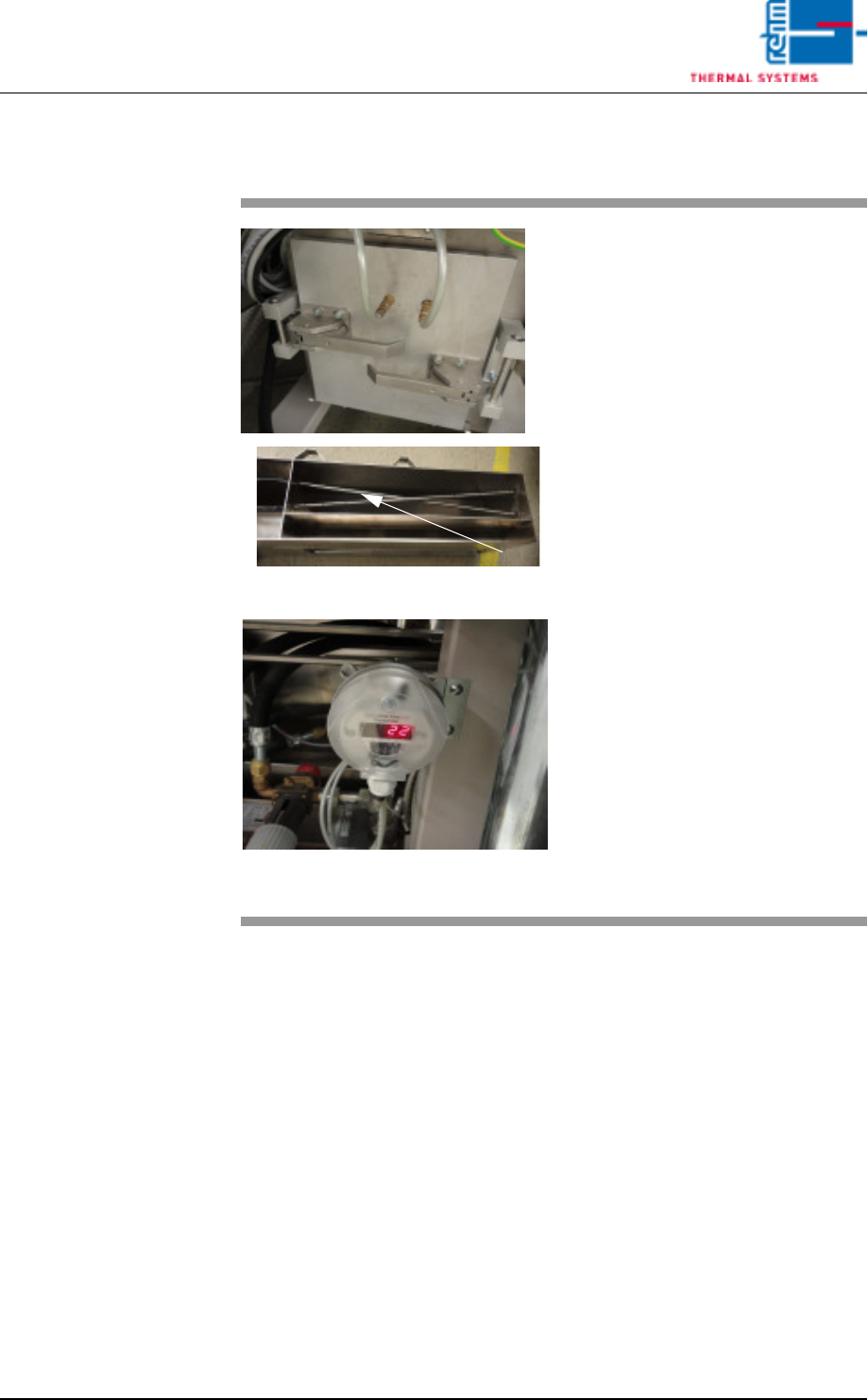
4.4.13 Volume flow control, cooling section (option)
Fig. 4-38 Volume flow measurement
Fig. 4-39 Differential pressure gauge for cvo-
lume flow measurement
The volume flow through the cooling
section is measured via dynamic
pressure drop.
Two dynamic pressure sensors are
to this end integrated at a defined
point in the air duct – as shown on
the right.
The first dynamic pressure sensor
records the total flow pressure.
The second dynamic pressure sen-
sor records the static pressure.
The differential pressure gauge indi-
cates the difference between these
two values.
The volume flow is calculated inter-
nally based on the known cross-
section and the gas temperature.
The actual volume flow is main-
tained by activating the volume flow
control function via the visualisation.