OperationInstruction_Vsision XP.pdf - 第147页
V ISION XP+ V AC Page 139 5 Software 5.6 The Protocol Menu Operating Instructions V ersion 1.5 5.6.2 D isplaying the Protocol as a T able Fig. 5-6 3 Disp laying the Protocol as a T able Recorded protocol data are disp la…

Page 138 VISION XP+ VAC
5 Software
5.6 The Protocol Menu
Operating Instructions
Version 1.5
G) Allocated Statuses
All statuses are listed which are to be included in the protocol when an
event occurs.
H) Exceptions
The exceptions function can be used to specify which additional
conditions must be fulfilled before an event is triggered. For example,
alarms such as “external cooling system” can be suppressed if the
system is equipped with internal cooling.
Status Window
– Value
Logging of the status along with an event
– Tolerance (the event only occurs if the tolerance range is exceeded or
fallen short of).
The user is able to define a special tolerance range for reporting
purposes. The upper and lower tolerances are specified relative to the
setpoint with Rel+ and Rel-. If the data point lies within the specified
tolerance range, it is logged as a positive result and is highlighted green.
If it does not lie within the specified tolerance range, it is logged as a
negative result and is highlighted red.
– Alarm range protocol
The alarm range protocol has the same function as the tolerance
protocol. However, setpoint parameters Rel+ and Rel- are taken from the
control channel, and depend upon the currently loaded program. Only
those data points can be selected which have been defined as control
channels.
– Exceptions
The exceptions function can be used to specify which additional
conditions must be fulfilled before an event is triggered. For example,
alarms such as “external cooling system” can be suppressed if the
system is equipped with internal cooling.
VISION XP+ VAC Page 139
5 Software
5.6 The Protocol Menu
Operating Instructions
Version 1.5
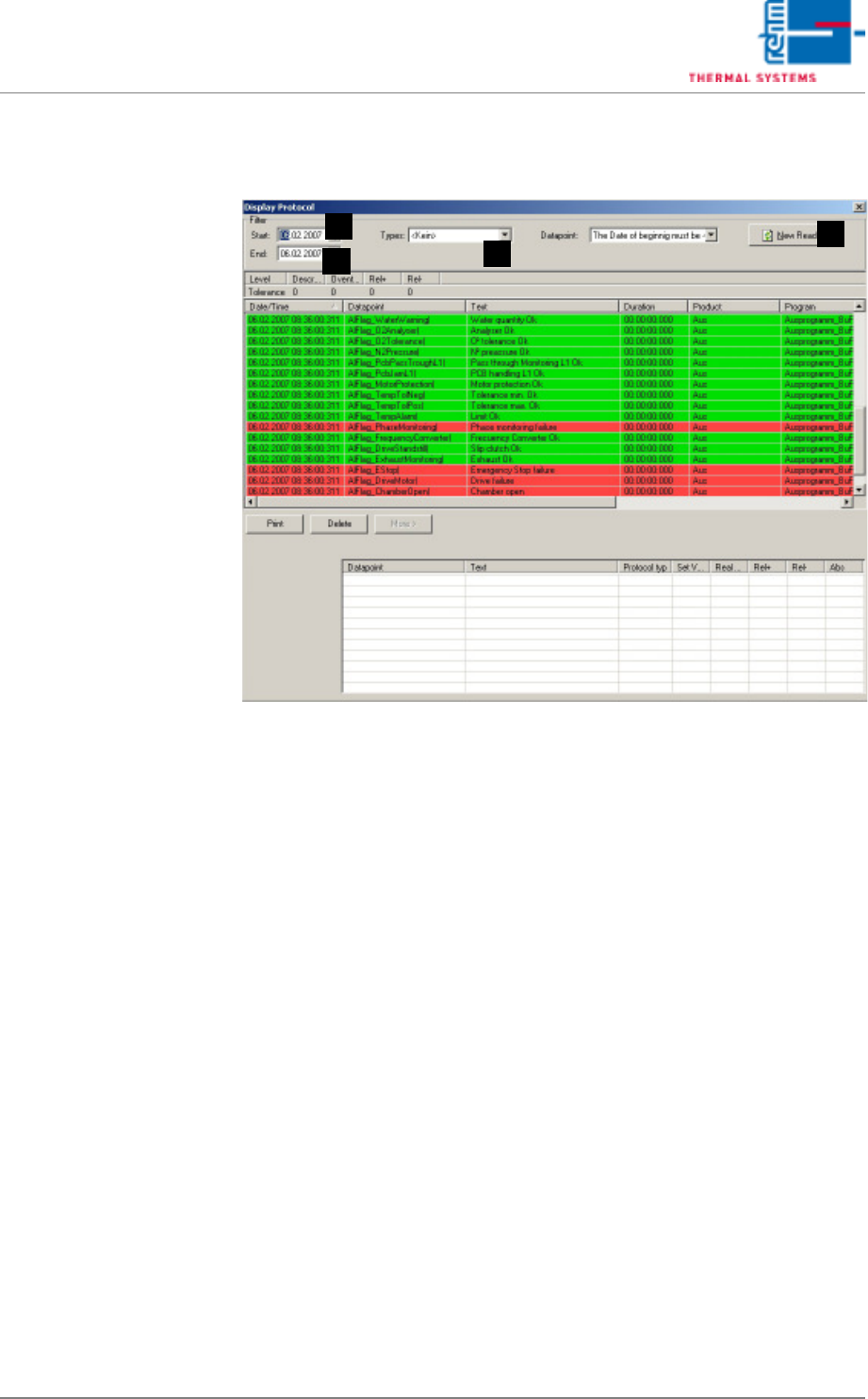
5.6.2 Displaying the Protocol as a Table
Fig. 5-63 Displaying the Protocol as a Table
Recorded protocol data are displayed.
A) Start
The point in time at which querying of stored protocol data begins.
B) End
The point in time at which querying of stored protocol data ends.
C) Types
Data filter, not used.
D) Read-In Button
Protocol data of the selected type are read in from the start date to the
end date when the read-in button is clicked.
A
D
C
B
Page 140 VISION XP+ VAC
5 Software
5.6 The Protocol Menu
Operating Instructions
Version 1.5
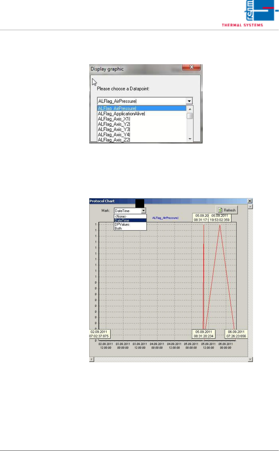
5.6.3 Graphic protocol display
Abb. 5-64 Graphic Protocol display
By selecting the submenu item “Graphic protocol display”, alarm status
changes can be graphically displayed in chart form, over a certain time.
Each status change is shown as 0 or 1, connected by a line. Various data
points may be selected.
Abb. 5-65 Protocol Chart
The exact time can also be shown in the graphic chart. Select “Date Time”
under Point A for this. Or only the “DPValues” data point might be displayed.
Or both together.
A