OperationInstruction_Vsision XP.pdf - 第77页
Vision XP+ V AC Page 69 4 Equipment 4.7 Exhaust Air System Operating Instructions V ersion 1.5 4.7 Exhaus t Air Sys tem 4.7.1 Ex haust Fan VXP+ (option) Fig. 4-5 0 Ex haust Air Sy stem wi th Connec- tion for a Plant Ex h…
Page 68 Vision XP+ VAC
4 Equipment
4.6 Condensate Trap
Operating Instructions
Version 1.5
4.6 Condensate Trap
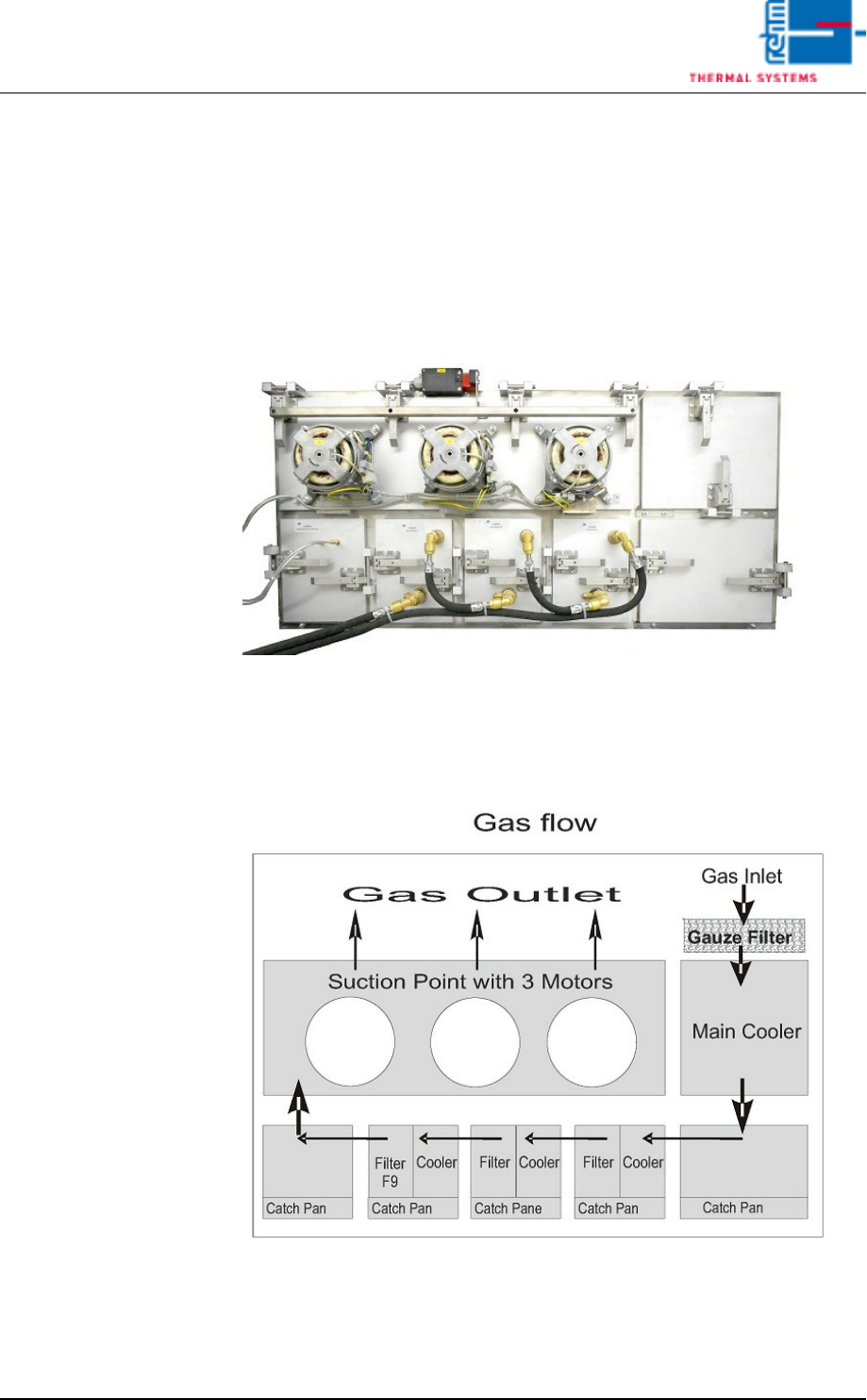
4.6.1 Condensate trap VXP+
The condensate trap (VXP+) is located on the back of the system under-
neath the cooling tract.
Fig. 4-48 Condensate Trap VXP+
Contaminated process gas is exhausted after the last peak zone and fed to
the condensate trap where it’s cooled down and purified. At the end of the
process it’s returned to the cooling tract.
Fig. 4-49 Flow of Gas Through the Condensate Trap VXP
Vision XP+ VAC Page 69
4 Equipment
4.7 Exhaust Air System
Operating Instructions
Version 1.5
4.7 Exhaust Air System
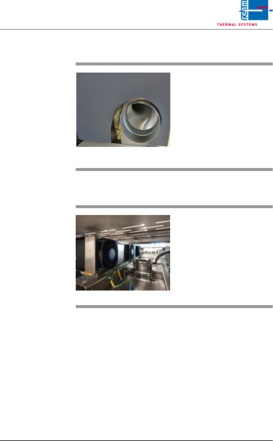
4.7.1 Exhaust Fan VXP+ (option)
Fig. 4-50 Exhaust Air System with Connec-
tion for a Plant Exhaust System
Exhaust air from the process is
drawn off at the inlet and the outlet.
It will be supplied to the internal ex-
haust system via the pipe.
Fig. 4-51 Exhaust fan VXP+
The trapped heat generated by the
process is drawn in by the exhaust
fans. The trapped heat is then
cooled by blowing through coolers.
The cooled air may now be recircu-
lated.
Page 70 Vision XP+ VAC
4 Equipment
4.8 Cooling System
Operating Instructions
Version 1.5
4.8 Cooling System
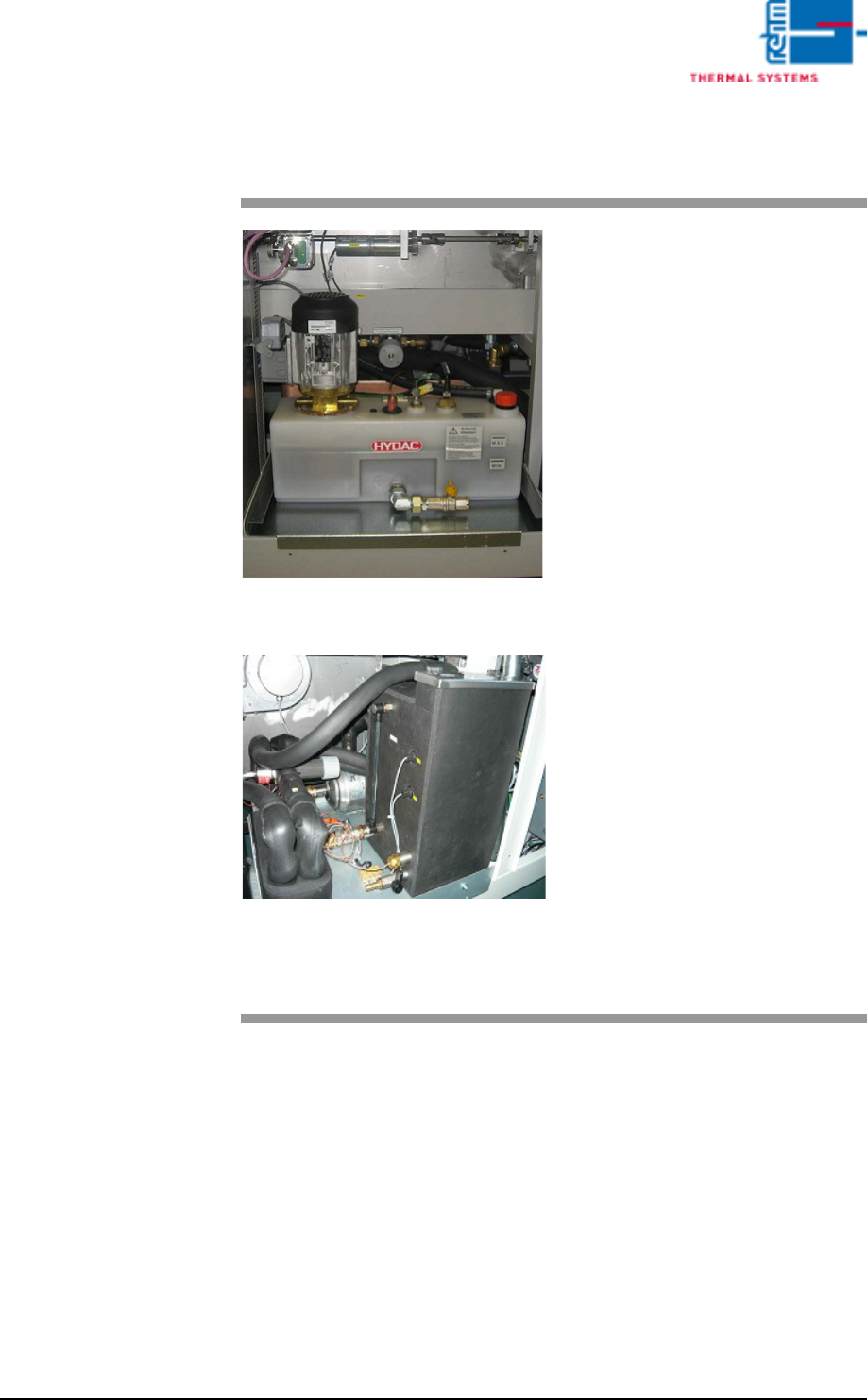
Fig. 4-52 Cooling system with integrated
coolant water pump
Fig. 4-53 Cooling system with integrated
coolant water pump CN
The cooling system is stored in a
tank made of plastic underneath the
last cooling zone.
Coolant water is pumped from the
coolant water tank into the coolant
circuits by a rotary pump.
The hot water subsequently flows
through the plate heat exchanger. It
is cooled down as a result, and is
then returned to the tank.
The level of the cooling water will be
controlled by means of two float
switch sensors.
One sensor monitors controlled the
minimum full-level. The sensor gen-
erates a „min. water level” message
which is displayed by the software
when the fill-level is too low. If the
fill-level drops below the second
sensor, it is assumed that the sys-
tem has a leak and the heat and the
water pump are shut down for safety
reasons.
An additional sensor monitors cool-
ant water temperature. It triggers
the „maximum temperature exceed-
ed” alarm message if the selected
upper limit is exceeded and
switched off the heating.