OperationInstruction_Vsision XP.pdf - 第76页
Page 68 Vision XP+ V AC 4 Equipment 4.6 Condensate T rap Operating Instructions V ersion 1.5 4.6 Condensa te T rap 4.6.1 Condensate trap VXP+ The condens ate trap (VXP+) is locate d on the back of t he system under- neat…
Vision XP+ VAC Page 67
4 Equipment
4.5 Pyrolysis System
Operating Instructions
Version 1.5
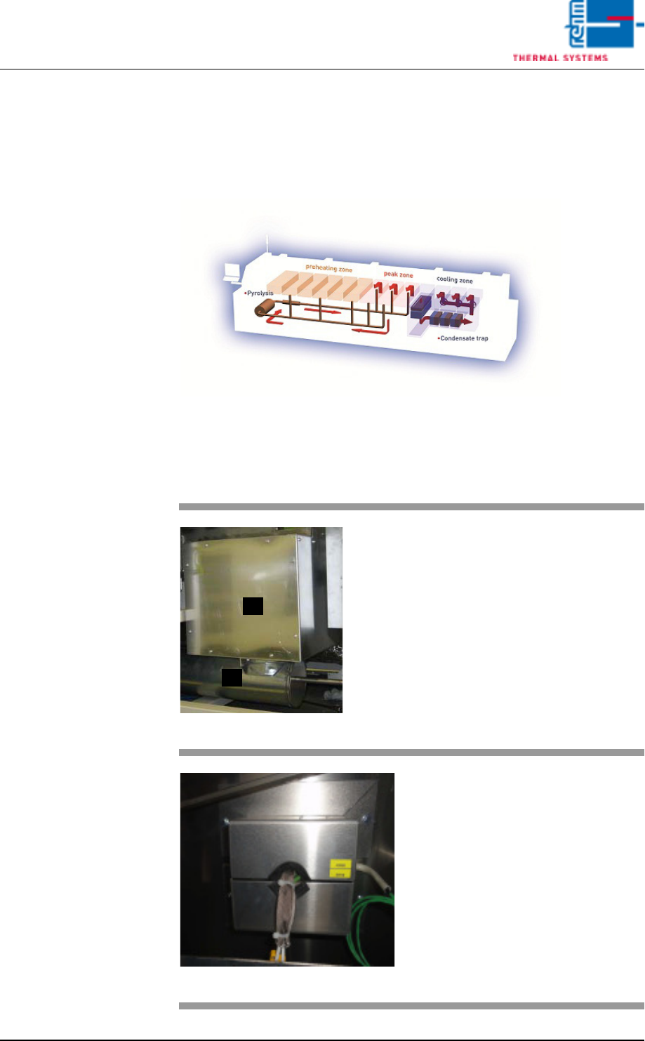
4.5 Pyrolysis System
Process gas which is contaminated during soldering is purified in the pyrol-
ysis unit and returned to the soldering process.
Fig. 4-45 Gas Flow in the Pyrolysis System
Contaminated gas is exhausted from preheating right on up to the peak
zone. The gas is then purified by means of pyrolysis and is blown back into
the peak zone.
Fig. 4-46 Pyrolysis System
A)Pyrolysis box
B)Venturi tube
The Venturi tube propels gas
through the pyrolysis system.
Throughput is measured by means
of the flow meter. The flow meter is
located on the adjusting panel for
nitrogen distribution (see Fig. 4-54).
Fig. 4-47 Pyrolysis Connections
• 3 heater connections
• 1 pc. connection for gas tempera-
ture Pyrolysis.
• 3 pc. temperature sensors
B
A
Page 68 Vision XP+ VAC
4 Equipment
4.6 Condensate Trap
Operating Instructions
Version 1.5
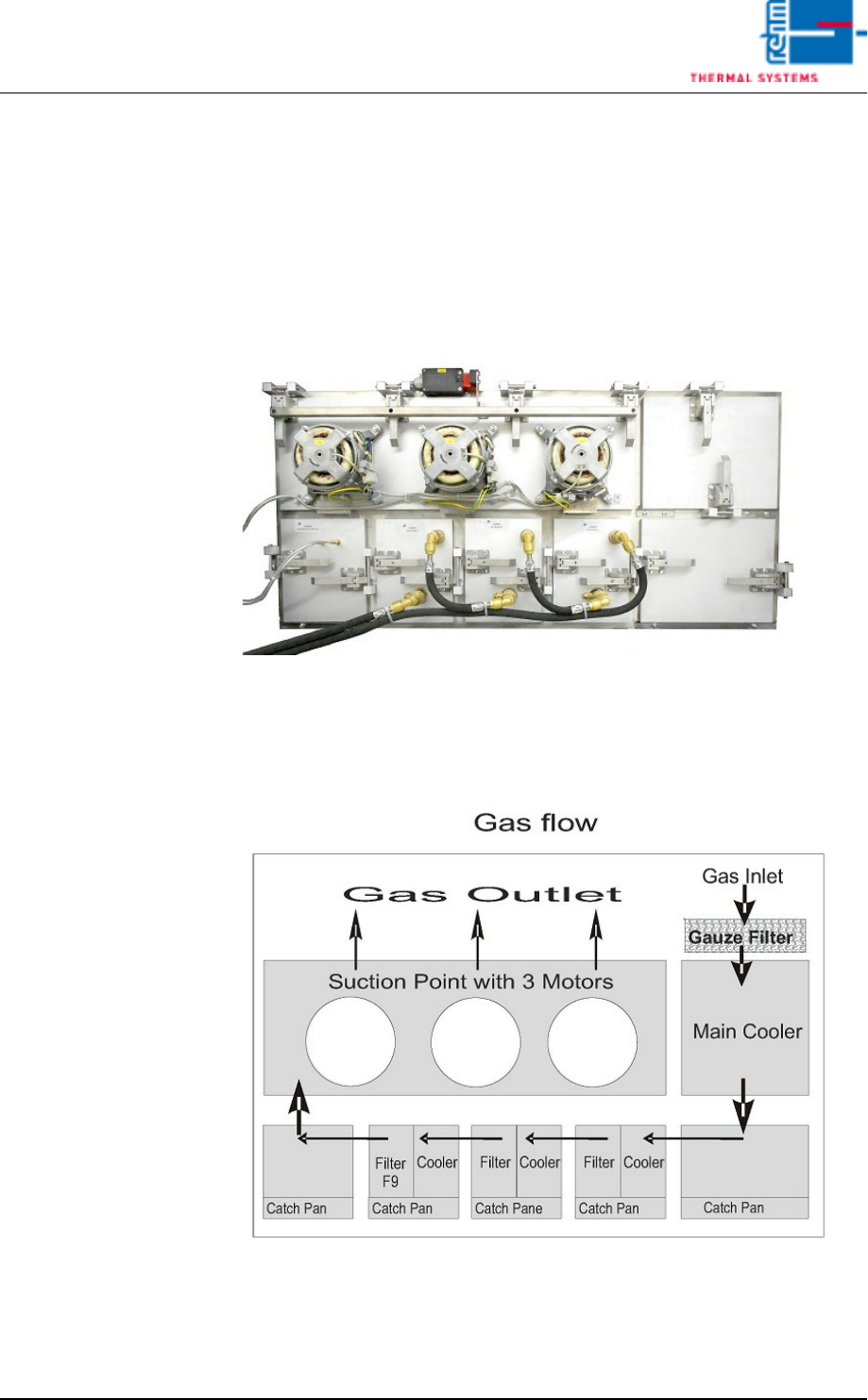
4.6 Condensate Trap
4.6.1 Condensate trap VXP+
The condensate trap (VXP+) is located on the back of the system under-
neath the cooling tract.
Fig. 4-48 Condensate Trap VXP+
Contaminated process gas is exhausted after the last peak zone and fed to
the condensate trap where it’s cooled down and purified. At the end of the
process it’s returned to the cooling tract.
Fig. 4-49 Flow of Gas Through the Condensate Trap VXP
Vision XP+ VAC Page 69
4 Equipment
4.7 Exhaust Air System
Operating Instructions
Version 1.5
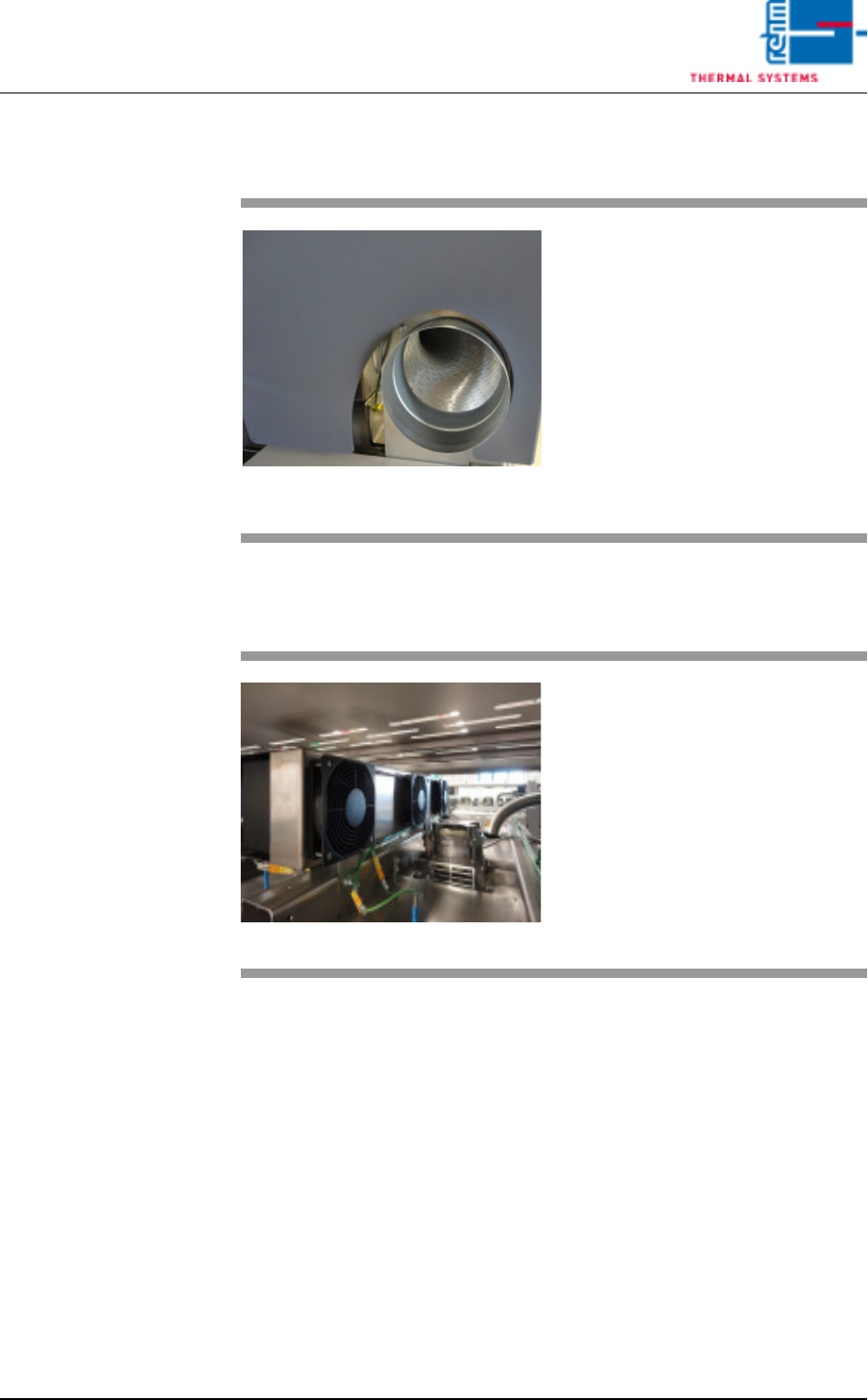
4.7 Exhaust Air System
4.7.1 Exhaust Fan VXP+ (option)
Fig. 4-50 Exhaust Air System with Connec-
tion for a Plant Exhaust System
Exhaust air from the process is
drawn off at the inlet and the outlet.
It will be supplied to the internal ex-
haust system via the pipe.
Fig. 4-51 Exhaust fan VXP+
The trapped heat generated by the
process is drawn in by the exhaust
fans. The trapped heat is then
cooled by blowing through coolers.
The cooled air may now be recircu-
lated.