OperationInstruction_Vsision XP.pdf - 第55页
Vision XP+ V AC Page 47 4 Equipment 4.2 Display Elements and Controls on the System Operating Instructions V ersion 1.5 The import ant function keys F1 Help function F2 Select next window F3 Select previous wi ndow F10 G…
Page 46 Vision XP+ VAC
4 Equipment
4.2 Display Elements and Controls on the System
Operating Instructions
Version 1.5
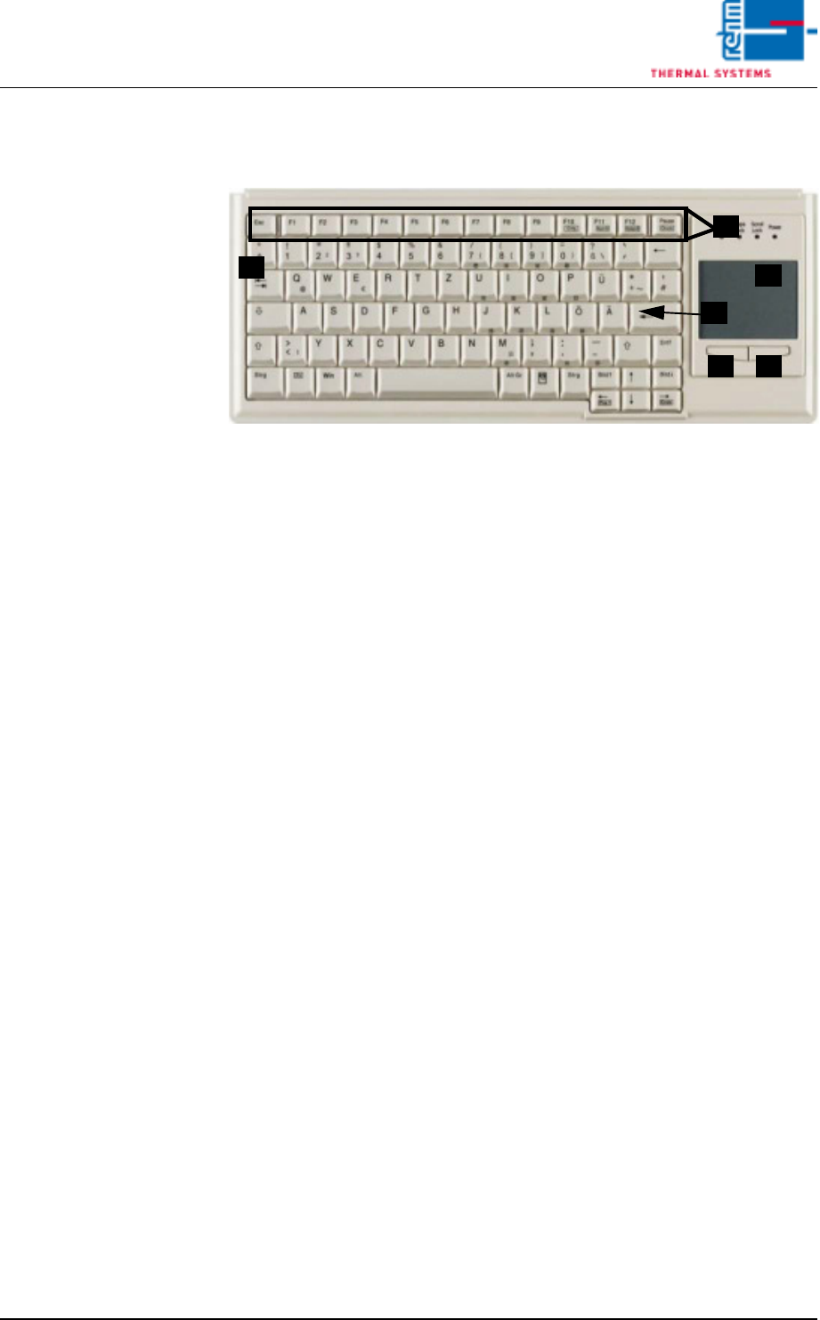
4.2.7 Keyboard
Fig. 4-9 Keyboard
A) Function keys F1 - F12
B) Tab key
C) Return key
D) Touchpad
E) Left mouse key
F) Right mouse key
The keyboard and the touchpad are used as standard input devices for the
graphic user interface furnished with the software.
Use a finger to move the arrow across the touch pad to the desired position
on the user interface. Use the left mouse button select and launch the rele-
vant function. Carrying out actions by pressing the left mouse button will be
referred to as clicking in this operating manual.
B
C
D
E F
A
Vision XP+ VAC Page 47
4 Equipment
4.2 Display Elements and Controls on the System
Operating Instructions
Version 1.5
The important function
keys
F1 Help function
F2 Select next window
F3 Select previous window
F10 Go to menu bar
Software-specific
function keys
Tab Jump forward from one field to the next
Shift + tab Jump backwards from one field to the next
Y (scroll up) To previous entry in a list
Z (scroll down) To next entry in a list
y (backspace) Delete the character to the left of the cursor
Delete Delete the character to the right of the cursor
Insert Toggle between insertion and overwrite modes
Home Jump to the beginning of the line in an entry field, or
to the beginning of a list
End Jump to the end of the line in an entry field, or to the
end of a list
Ctrl + Home Jump to first field
Ctrl + End Jump to last field
Ctrl + Delete Delete a field
Page Z Jump to the next page of a list
Enter Actuating a field; selection from a list
Space Actuating a button
Esc Exit a window
Note!
A separate set of keyboard operating and service instructions is also pro-
vided which includes descriptions of keys, displays and setup options.
Please observe the maintenance instructions and user tips included in
these instructions.
Page 48 Vision XP+ VAC
4 Equipment
4.3 Conveyor System
Operating Instructions
Version 1.5
4.3 Conveyor System
The system is equipped with a single lane conveyor as standard equipment.
Dual lane (double conveyor) and multi-track conveyors can be supplied as
options.
Please refer to the data sheet which is included in the documentation regard-
ing conveyor system technical data. These data make reference to standard
conveyor systems, and may deviate slightly depending upon included equip-
ment.
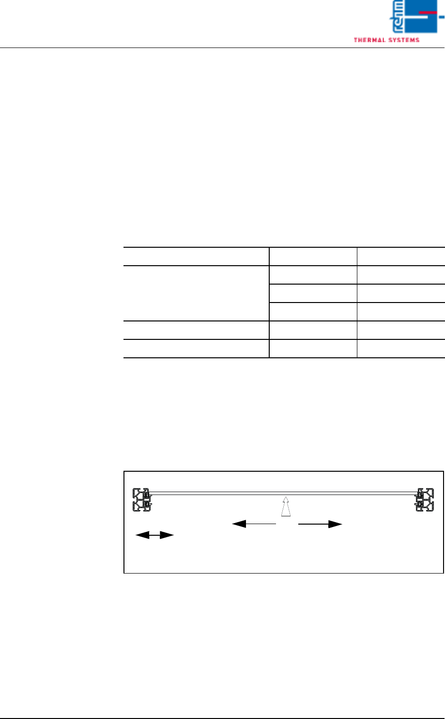
4.3.1 Conveyor types
Tab. 4-1 Modes of Conveyor
Conveyor width can be adjusted with a software button, or automatically by
entering the width of the PCB at the PC. Safety limit switches prevent viola-
tion of minimum and maximum widths.
Single conveyor
Conveyor type without CS
a
a. CS = Center Support
with CS A
Single Lane 50-400 mm 55-400 mm
50-460 mm 55-460 mm
50-508 mm 55-508 mm
Dual Lane 50-216 mm 65-216 mm
Multitrack 50-216 mm 65-216 mm
Center Support
(CS)
Adjustable Side Panel
Fixed Side
Operating Side
1
2
Panel