OperationInstruction_Vsision XP.pdf - 第200页
Page 192 V ISION XP+ V AC 7 Alarm Messages 7.33 Residual Oxygen Meter Malfunction Operating Instructions V ersion 1.5 7.33 Residual Oxygen Meter Mal function 7.34 O² toleran ce warni ng Advance warn ing for Residual oxyg…
VISION XP+ VAC Page 191
7 Alarm Messages
7.30 Cooling system failure (option)
Operating Instructions
Version 1.5
7.30 Cooling system failure (option)
External cooling
Procedure:
• Check external cooling equipment. Switch on or repair external cooling
equipment.
• Check temperature setpoint and hysteresis. Correct selected values.
• Check coolant water level and replenish if necessary.
7.31 N2 consumption OK / too high (option)
Only with N2 consumption measuring. In the „Consumption Parameter“
mask a limit value is set. If it is exceeded, the alarm is triggered off (not in
the flushing phase).
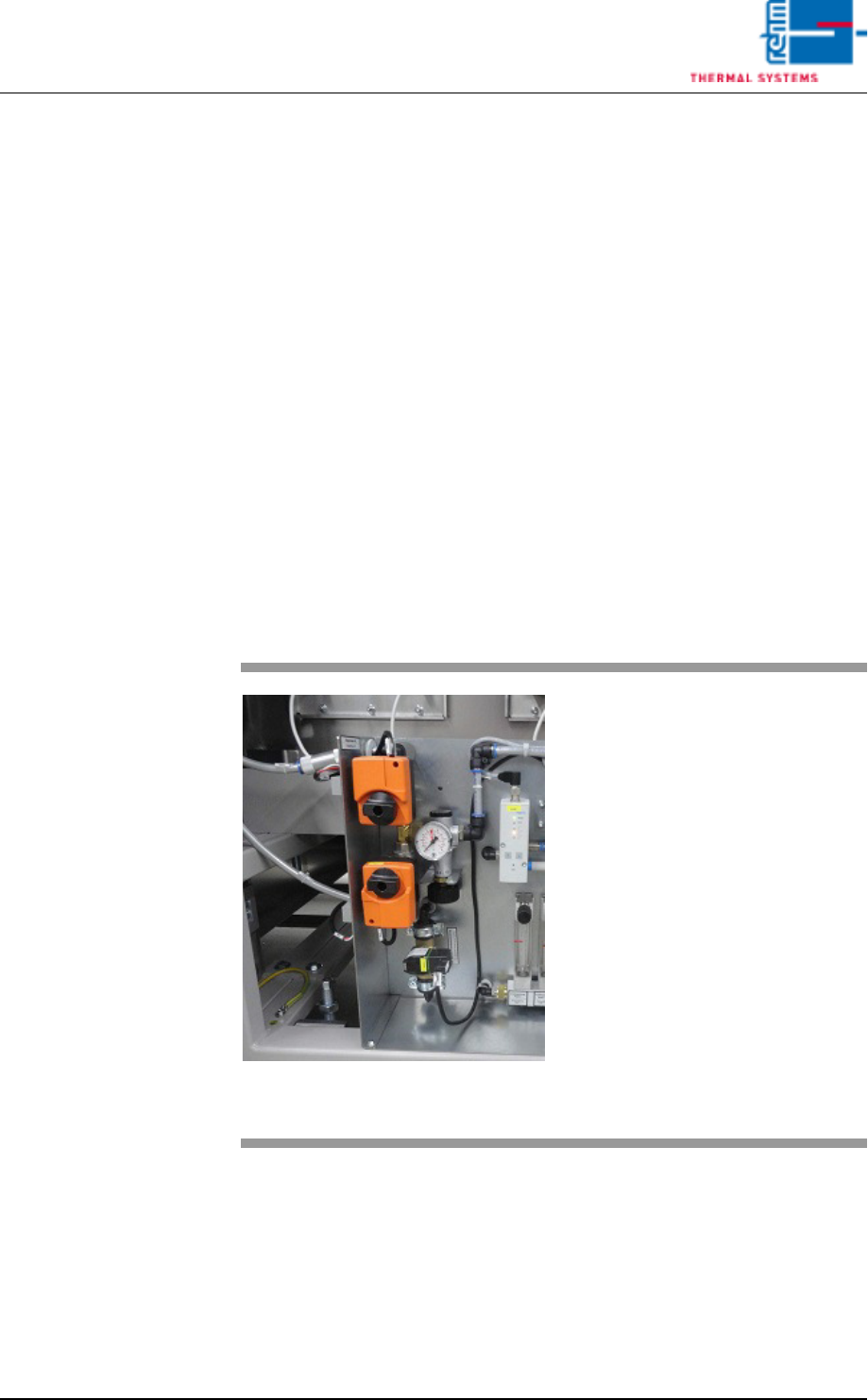
7.32 N2/O2 Pressure Too Low (option)
Fig. 7-22 Servomotor, Main N2 Supply Line
The alarm is only activated in the
event of operation with nitrogen.
Possible causes:
• Gas pressure is too low or nonex-
istent.
• Supply pressure has fallen below
the selected alarm value.
• The heat is turned off. The Belimo
servomotor in the main N2/O2
supply line is closed.
Procedure:
• Inspect the N2/O2 supply line.
• 5bar Control
• 3m³/h pyrolyses
Page 192 VISION XP+ VAC
7 Alarm Messages
7.33 Residual Oxygen Meter Malfunction
Operating Instructions
Version 1.5
7.33 Residual Oxygen Meter Malfunction
7.34 O² tolerance warning
Advance warning for Residual oxygen valve.
7.35 O
2
Tolerance injury
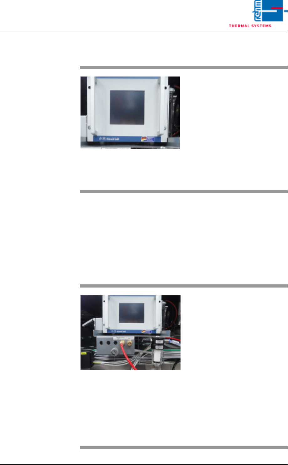
Fig. 7-23 Residual Oxygen Meter
An error has occurred at the residu-
al oxygen meter.
Possible causes:
• Flow is impaired.
• The filter at the residual oxygen
meter is contaminated.
• Residual oxygen meter is defect
Please refer to the included docu-
mentation regarding the
residual oxygen meter for additional
details.
Fig. 7-24 Nitrogen Connections and Residu-
al Oxygen Meter
The residual oxygen value in the
heating chamber has exceeded the
value set in the N2 operation mask
limit tolerance value.
Possible causes:
• Inadequate maintenance.
• The nitrogen settings are incor-
rect. Check the fixed settings in
the calibration report!
• One of the process chamber
seals is leaky.
• The residual oxygen meter is
hooked up incorrectly (standard:
peak zone).
• The filter bowl in the peak zone is
contaminated.

VISION XP+ VAC Page 193
7 Alarm Messages
7.36 Vacuum process OK
Operating Instructions
Version 1.5
7.36 Vacuum process OK
The alarm is triggered as the desired pressure was not reached within the
allowed time.
The vacuum chamber is not closed properly.
The pre-entered time to draw the vacuum is not reached.
Procedure:
• Check the vacuum chamber for any objects.
• Check the supply pressure.
• Adjust time.
• Check the malfunction of the vacuum pump
• The valves do not work properly.
7.37 Vacuum pumpe OK
The alarm is triggered when the vacuum pump is showing a malfunction.
Procedure:
• Check vacuum pump.
7.38 PCB length (vacuum process)
The alarm is triggered as soon as the PCB (printed circuit board) exceeds a
maximum specified length. The vacuum process cannot take place because
the board length exceeds the size of the chamber.
7.39 Sensor fault
The alarm is triggered as soon as the existing sensors are contaminated with
dirt.
Possible causes:
• Sensors are faulty
• Sensors are not set correctrly.
Procedure:
• Replace sensors.
• Set the sensors correctly.
• Clean the sensors.