HS50_advance_level 2.pdf - 第100页
07/2002 Editio n Student G uide HS -50 Advanc ed II 3 Power Sup ply 62 ➠ Loosen the M5 hex agon n uts (1) and remove togethe r with the retainin g rings (2). ➠ Remove the perspex panel (3) . ➠ Detach the ter minal wir …
Student Guide HS-50 Advanced II 07/2002 Edition
3 Power Supply
61
➠ Connect the placement system to the power supply.
➠ Measure the voltages at the main power filter’s input and output:
3 x 204 VAC / 3 x 230 VAC / 3 x 380 VAC / 3 x 400 VAC / 3 x 415 VAC
➠ Complete the servicing work as described in 3.3.3 on page 3 - 29.
5HSODFLQJWKHLQUXVKFXUUHQWOLPLWDWLRQERDUG(67
7RROVDQGHTXLSPHQW
– Set of slotted-head screwdrivers
– Open-ended spanner or socket spanner, size 8
– Self-adhesive labels
– Digital voltmeter
3DUWV
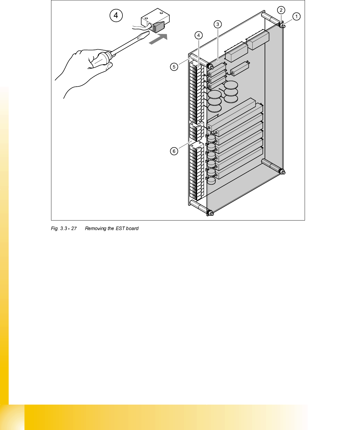
5HPRYLQJWKH(67ERDUG
DANGER Switch off the placement system and disconnect from the power
supply (see sections 3.3.1 and 3.3.2).
3RVLWLRQ 'HVLJQDWLRQ ,WHPQXPEHU
EST Inrush current limitation board TG 31033-01 00341831-01
07/2002 Edition Student Guide HS-50 Advanced II
3 Power Supply
62
➠ Loosen the M5 hexagon nuts (1) and remove together with the retaining rings (2).
➠ Remove the perspex panel (3).
➠ Detach the terminal wires from the terminal block one by one by pushing the terminal link (4)
in the direction indicated by the arrow.
➠ Identify the terminal wires with adhesive labels.
➠ Remove the M5 hexagon bolts.
➠ Remove the board.
)LWWLQJWKH(67ERDUG
➠ Fit the board and fix in place with M5 hexagon bolts.
➠ Connect up the terminal wires.
➠ Attach the perspex panel and fix in place with the retaining rings and M5 hexagon nuts.

Student Guide HS-50 Advanced II 07/2002 Edition
3 Power Supply
63
PLEASE NOTE:
Do not overtighten the M5 hexagon head screws: the panel might break.
➠ Switch the placement system on. Main contactor SZ1 will pick up.
➠ Measure the 30 VDC control voltage between terminals A1 (+) and A2 (-) on the main contactor
SZ1.
➠ Complete the servicing work as described in 3.3.3 on page 3 - 29.