HS50_advance_level 2.pdf - 第248页
07/2002 Editio n Student G uide HS -50 Advanc ed II 8 Y-Axis 30 $ Q DOR J7 U DFN6LJ QDO V* DQWU \ $ [HV 0HDVXUHPHQW6HWXSRI$ QDORJ7 UDFN6LJQDOV 2VFLOORVFRSH6HWWLQ JV Inkrementalgeber X- …

Student Guide HS-50 Advanced II 07/2002 Edition
8 Y-Axis
29
&KHFNLQJWKHWUDFNVLJQDO
7HVW(TXLSPHQW
1 dual channel oscilloscope > 20 MHz
– 1 track signal tester HS-50.
– Plastic feeler gauge 0.4 mm
2YHUYLHZ
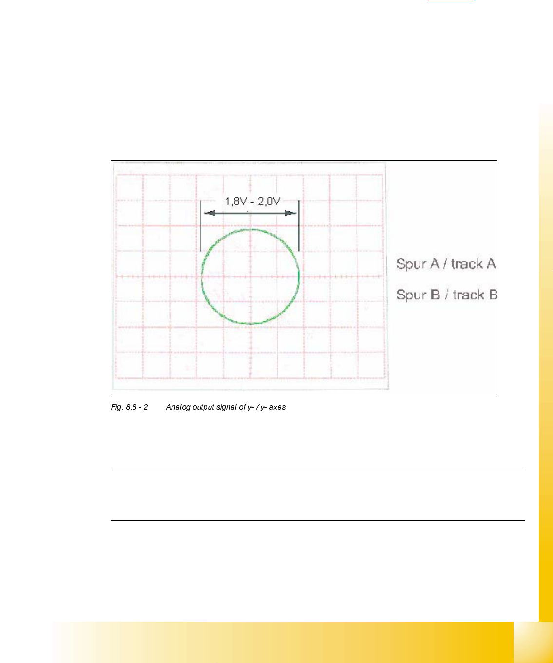
$[HV 6HWWLQJ 2VFLOORVFRSH'LVSOD\
X read head adjusted to
0.4 mm,
parallel to scale
analog track signals:
digital track signal:
circuit with 1.8 V
diameter
pulse signals with
3.6 V
ss
and
90° degree phase
offset
Y read head adjusted to
0.4 mm,
parallel to scale
analog track signals:
digital track signal:
circuit with 1.8 V
diameter
pulse signals with
3.6 V
ss
and
90° degree phase
offset
07/2002 Edition Student Guide HS-50 Advanced II
8 Y-Axis
30
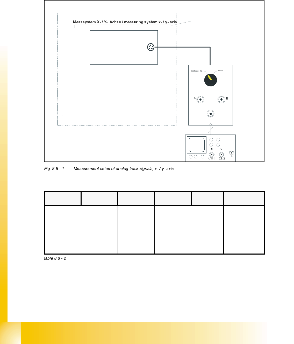
$QDORJ7UDFN6LJQDOV*DQWU\$[HV
0HDVXUHPHQW6HWXSRI$QDORJ7UDFN6LJQDOV
2VFLOORVFRSH6HWWLQJV
Inkrementalgeber X- / Y- Achse /
incremental encoder x- / y- axis
SIPLACE HS-50
Auflösung des Maßstabes: 1 Digit = 1 m
measuring scale: 1 dgt = 1 m
µ
µ
Spursignal - Teste
r /
track signal tester
BNC - Leitung
BNC line
track
zero pulse
analog
&KDQQHO 6LJQDO &RXSOLQJ <'HIOHFWLRQ 7ULJJHU ;'HIOHFWLRQ
CH 1
track A of
track signal
tester
DC 0.5 V/ DIV
x- / y- mode
auto 5 ms/ DIV
CH 2
track B of
track signal
tester
DC 0.5 V/ DIV
x- / y- mode
Student Guide HS-50 Advanced II 07/2002 Edition
8 Y-Axis
31
3URFHGXUH
➠ Turn on the machine.
➠ Relate your measurement setup to the x-, or y- axis respectively. (See Fig. 8.9 - 3).
➠ Adjust the oscilloscope.
➠ Set the track signal tester to the "Oscilloscope cal" position.
➠ With the help of the positioning switches CH1 and CH2, move the light spot exactly to the
center of the crosshairs of the screen.
➠ Set the track signal tester to the "signal output" position.
➠ Manually, move the appropriate axis (x = head / y = gantry) back and forth.
– If you adjusted the read head correctly, the following illustration will appear on the screen of
the oscilloscope:
$QDORJH=HUR3XOVHRIWKH*DQWU\$[HV
NOTE
The pulse width of the analog zero pulse is dependent on the speed at which the axis is
traversed.