HS50_advance_level 2.pdf - 第417页
Stud ent Gu ide HS-5 0 Adva nced II 07/2 002 Ed ition 14 Conve yor System 43 ,QVW DOOLQJW KH6 WHSSLQJ0RWRUI RUWKH:LG WK$ GMX VWPHQW6 \ VWHP CA UTIO N O The new t oothed b elt is not to be stretched or …
07/2002 Edition Student Guide HS-50 Advanced II
14 Conveyor System
42
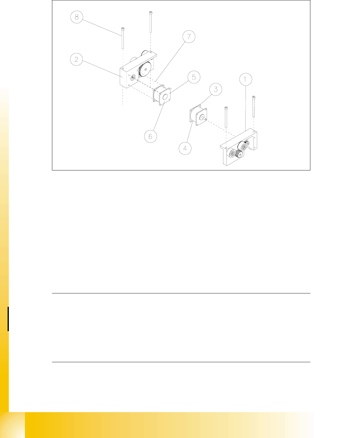
Fig. 14.3.8 Removing the Motor of the Width Adjustment System or the Drive of the Width Adjust. System (Complete)
Key to Fig. 14.3.8
➠ In the cable duct, disconnect the plug-and-socket connection for this motor of the width adjust-
ment system (;RU;: see circuit diagram for "6/,2PRGXOHRQ3&%FRQYH\RU
or RQ3&%FRQYH\RU.
NOTE:
If you have discovered a break in the motor cable during a continuity check and this break is up-
stream of the plug-and-socket connection, the motor cable must be run on a weaving course as
far as the "conveyor control PCB 1" / "... PCB 2" (see ) and unplugged at the connector X3 of
the corresponding "conveyor control" (see above-mentioned circuit diagram). This may be some-
what complicated due to the routing of the cable inside the machine base.
You may wish to contact Siemens SMD Service regarding this work. 14
➠ Pull the motor out of the drive housing.
1) Drive for width adj. system (complete)
(incl. Pos. 3 and 4 or 5 and 6)
2) Drive housing for width adj. system for con-
veyor 1 and 2
3) Motor width adj. system conveyor 1 4) Cable for motor width adj. system conv. 1
5) Motor width adj. system conveyor 2 6) Cable for width adj. system conveyor 2
7) Screws to fasten the motor:
4 hexagonal socket head cap screws M 3
8) 2 hexagonal socket head cap screws
M 6 x 80

Student Guide HS-50 Advanced II 07/2002 Edition
14 Conveyor System
43
,QVWDOOLQJWKH6WHSSLQJ0RWRUIRUWKH:LGWK$GMXVWPHQW6\VWHP
CAUTION O
The new toothed belt is not to be stretched or kinked. 14
➠ Install the new stepping motor in the reverse order to that described above for the removal. Bolt
the motor to the drive housing.
➠ Check: The HQWLUHZLGWKof the toothed belt must be engaged on the synchronizing disk
➠ Remove all tools, etc., from the working area of the machine.
➠ Make certain that the transmission lever on the lifting table motor mount is folded onto the lift-
ing curve (see Fig. 14.3.5, illustration bottom left).
➠ Re-install the lifting table as described in section 14.3.8.2.
➠ Carry out the appropriate )LQDOVWHSVLQFOXGLQJWKHIXQFWLRQFKHFN(see section 14.4).
During the function check, move the conveyor to its maximum and minimum width.
([FKDQJLQJWKH'ULYHIRUWKH:LGWK$GMXVWPHQW6\VWHP&RPSOHWH
NOTE:
Exchange the entire unit "Drive for width adjustment system", e.g., in case of a fault in the ball
bearing/syconronizing disks and motor. 14
([FKDQJLQJWKH'ULYHIRUWKH:LGWK$GMXVWPHQW6\VWHP&RPSOHWH
➠ Remove the lifting table as described in section 14.3.8.1.
➠ Relieve the stress on the large toothed belt for the width adjustment system as described
above in section 14.3.12.1 .
Take the large toothed belt off the sprocket wheels of the drive unit.
➠ Detach the plug-and-socket connection of the motor of the width adjustment system LQWKHFD
EOHGXFWas described above in section 14.3.13.1.
➠ Undo and remove the screws fastening the drive housing to the assembly base plate (2 hex-
agonal socket head cap screws M6: see Fig. 14.3.8 -> 8). Lift the "Drive for the width adjust-
ment system" out.
,QVWDOOLQJWKH'ULYHIRUWKH:LGWK$GMXVWPHQW6\VWHP&RPSOHWH
➠ Install the new "Drive for the width adjustment system" in the reverse order to that following
during removal.
➠ Place the large toothed belt for the width adjustment system on the deflection pulleys.
➠ Check: The HQWLUHZLGWKof the toothed belt must be engaged on the two outside synchronizing
disks (on the pedestal) and must be in contact with the circumference of the deflection pulleys.

07/2002 Edition Student Guide HS-50 Advanced II
14 Conveyor System
44
➠ 3ODFHWKHODUJHWRRWKHGEHOWXQGHUWHQVLRQ as described in section 14.3.12.2 for the instal-
lation of the "Toothed belt for the width adjustment system".
➠ Remove all tools, etc., from the working area of the machine.
➠ Make certain that the transmission lever on the lifting table motor mount is folded onto the lifting
curve (see Fig. 14.3.5, illustration bottom left).
➠ Where applicable, re-install the lifting table as described in section 14.3.8.2.
➠ Carry out the pertinent )LQDOVWHSVLQFOXGLQJIXQFWLRQFKHFN(see section 14.4). During the
function check, move the conveyor to its maximum and minimum width.
([FKDQJLQJWKH/LPLW6ZLWFKHVRIWKH:LGWK$GMXVWPHQW6\VWHP
5HPRYLQJWKH/LPLW6ZLWFKHVRIWKH:LGWK$GMXVWPHQW6\VWHP
NOTE:
The limit switches are preassembled including the cables. Nevertheless, the wiring can also be
unsoldered/soldered right at the switch in question if you discover that the limit switch itself is
faulty. 14
➠ Remove the lifting table as described in section 14.3.8.1.
➠ Mark the position of the limit switch on the rail with a fine permanent marker.
➠ Unsolder the connection wires on the faulty limit switch (allocation: see circuit diagram &RQ
YH\RUFRQWURO3&% or 3&%. Comply with the NOTE below.
➠ Remove the faulty limit switch (two M2 slotted screws: see Fig. 14.3.9 -> 7 -10).
NOTE:
If you have discovered a break in the limit switch cable during a continuity check, the cable must
be run on a weaving course as far as the corresponding "Conveyor Control PCB 1" / "... 2" (al-
location: see ) and must be unplugged there at connector X12 / X13 (see above-mentioned circuit
diagram).
This may be somewhat complicated depending on the cable routing inside the machine base.
You may wish to contact Siemens SMD Service regarding this work. 14