HS50_advance_level 2.pdf - 第46页
07/2002 Editio n Student G uide HS -50 Advanc ed II 3 Power Sup ply 8 3RZHU 6XSSO\XQLW 0DLQ6XSS O\YROW DJ HV Power Sup pl y Unit Ex terna l Sup pl y Eur ope : 3 x 400V Amer i c as : 3 x 20 4V Ot her: 3…
Student Guide HS-50 Advanced II 07/2002 Edition
3 Power Supply
7
3RZHU6XSSO\
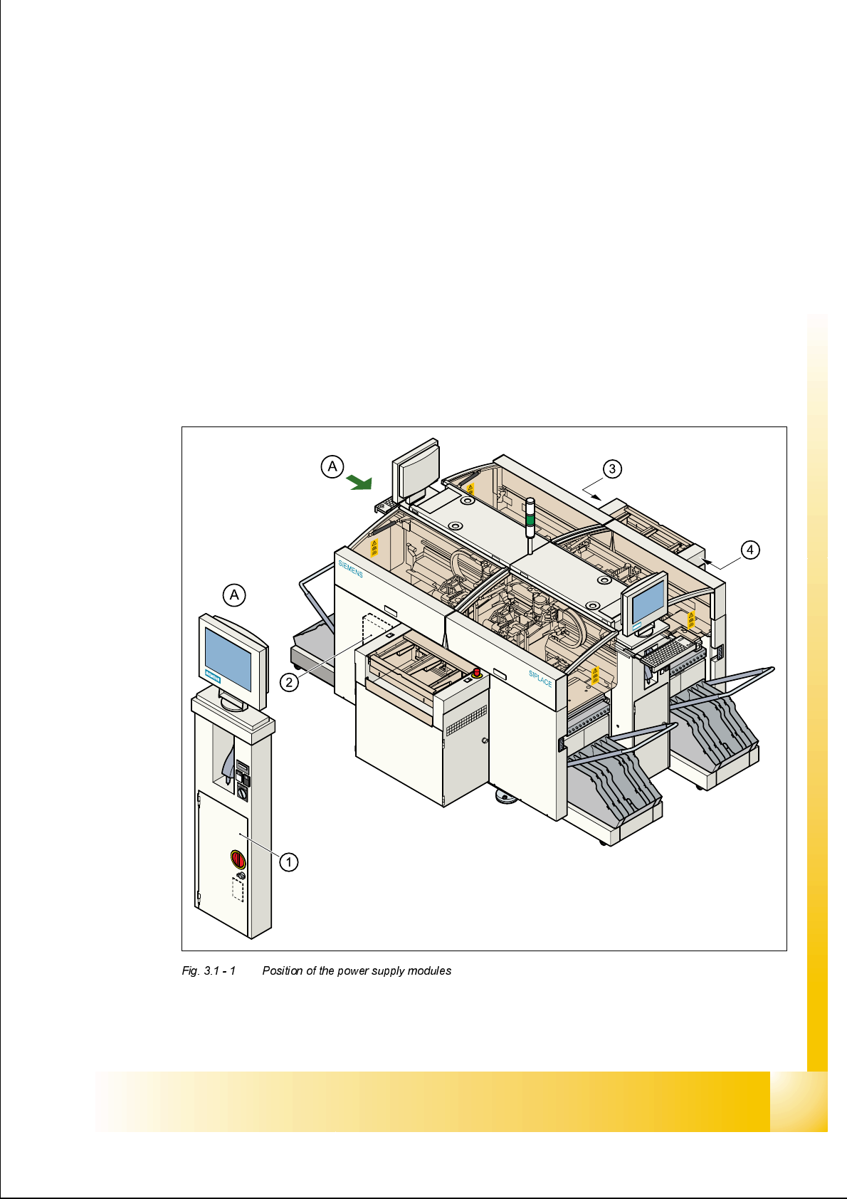
3RVLWLRQRIWKHSRZHUVXSSO\PRGXOHV
The diagram below shows the position of the modules that generate or distribute the power
needed to operate the placement system:
– Power supply unit (Pos. 1)
– Main distribution unit (Pos. 2)
– Control unit (Pos. 3)
– Servo unit (Pos. 4)
07/2002 Edition Student Guide HS-50 Advanced II
3 Power Supply
8
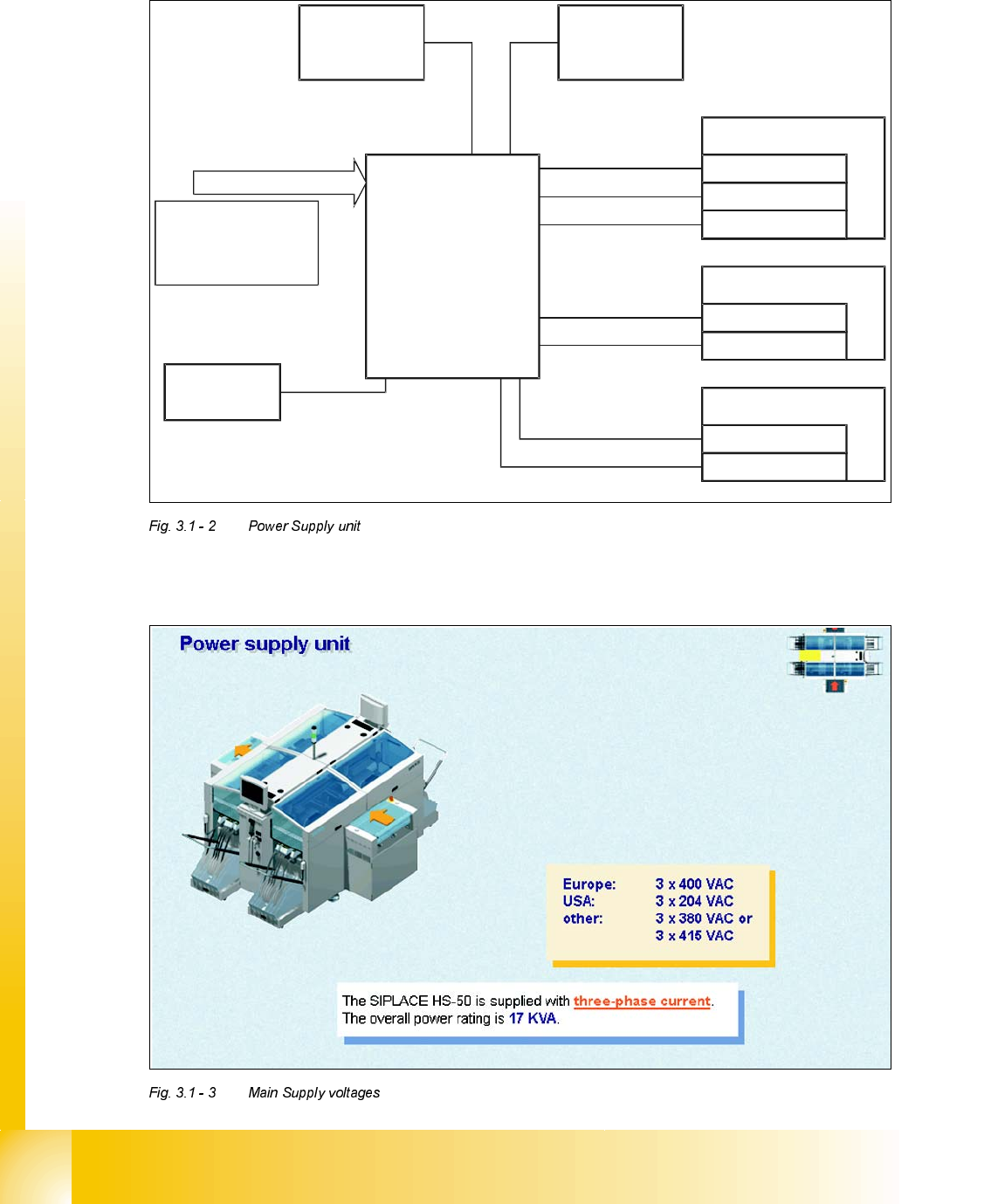
3RZHU6XSSO\XQLW
0DLQ6XSSO\YROWDJHV
Power Supply Unit
External Supply
Europe: 3 x 400V
Americas: 3 x 204V
Other: 3 x 380V or
3 x 415V
Control Unit
Servo Unit
Transport System
Component Table
Station
Computer +
Monitors
Z/DP Axes
Star Axes
X/Y Axes
Control Unit
Feeder Supply
Conveyor Motors
Lifting Tables
Service Plug

Student Guide HS-50 Advanced II 07/2002 Edition
3 Power Supply
9
6XSSO\YROWDJHV
The power supply unit is located in the left-hand middle section of the placement system. A lock-
able door prevents access to the unit.
The power supply unit provides the following supply voltages:
– 200 VDC for the servo amplifiers of the x and y axes
– 100 VDC/4 VDC for the servo amplifiers of the star
– 30 VDC for the servo amplifiers the z and dp axes
– 52 VDC for the DC/DC converters in the control unit
– 40 VDC for the component tables and the PCB handling system
– 10 VDC for the component tables
– 3 x 230 VAC for the lifting table motors of the single or dual conveyor (option)
– 230 VAC for the UPS for the station computer and monitors
For the service socket
PLEASE NOTE: The service socket can only be used if the placement system is con-
nected to the main power supply with a 5-conductor cable (L1, L2, L3, N, PE).
9ROWDJHVLQWKHSRZHUVXSSO\XQLWDIWHUVZLWFKLQJRQDWWKHPDLQVZLWFK
When the main switch is switched on, the following voltages are generated and may or may not
be switched through to the modules:
230 VAC (Europe) Input 3 x 400 VAC
115 VAC (U. S. A.) Input 3 x 204 VAC
130 VAC (other) Input 3 x 230 VAC
220 VAC (other) Input 3 x 380 VAC
240 VAC (other) Input 3 x 415 VAC
Voltage Module
200 VDC Servo unit Not enabled
100 VDC Servo unit Not enabled
4 VDC Servo unit Enabled
30 VDC Servo unit Enabled
52 VDC Control unit Enabled
40 VDC Component tables, PCB handling system Enabled
10 VDC Component table Enabled
3 x 230 VAC Lifting table motors Not enabled
230 VAC Station computer and PC Enabled
230 or 115 or 240 VAC Service socket Independent of the main switch