HS50_advance_level 2.pdf - 第257页
Stud ent Gu ide HS-5 0 Adva nced II 07/2 002 Ed ition 8 Y- Axis 39 0HDVXUH PHQW6HWXS IRU$ [LV$ GMXVWPHQW V NOTE The curr ent valu e meas ured at th e adapte r board is actua l, not (commute d) nomin al. axis …
07/2002 Edition Student Guide HS-50 Advanced II
8 Y-Axis
38
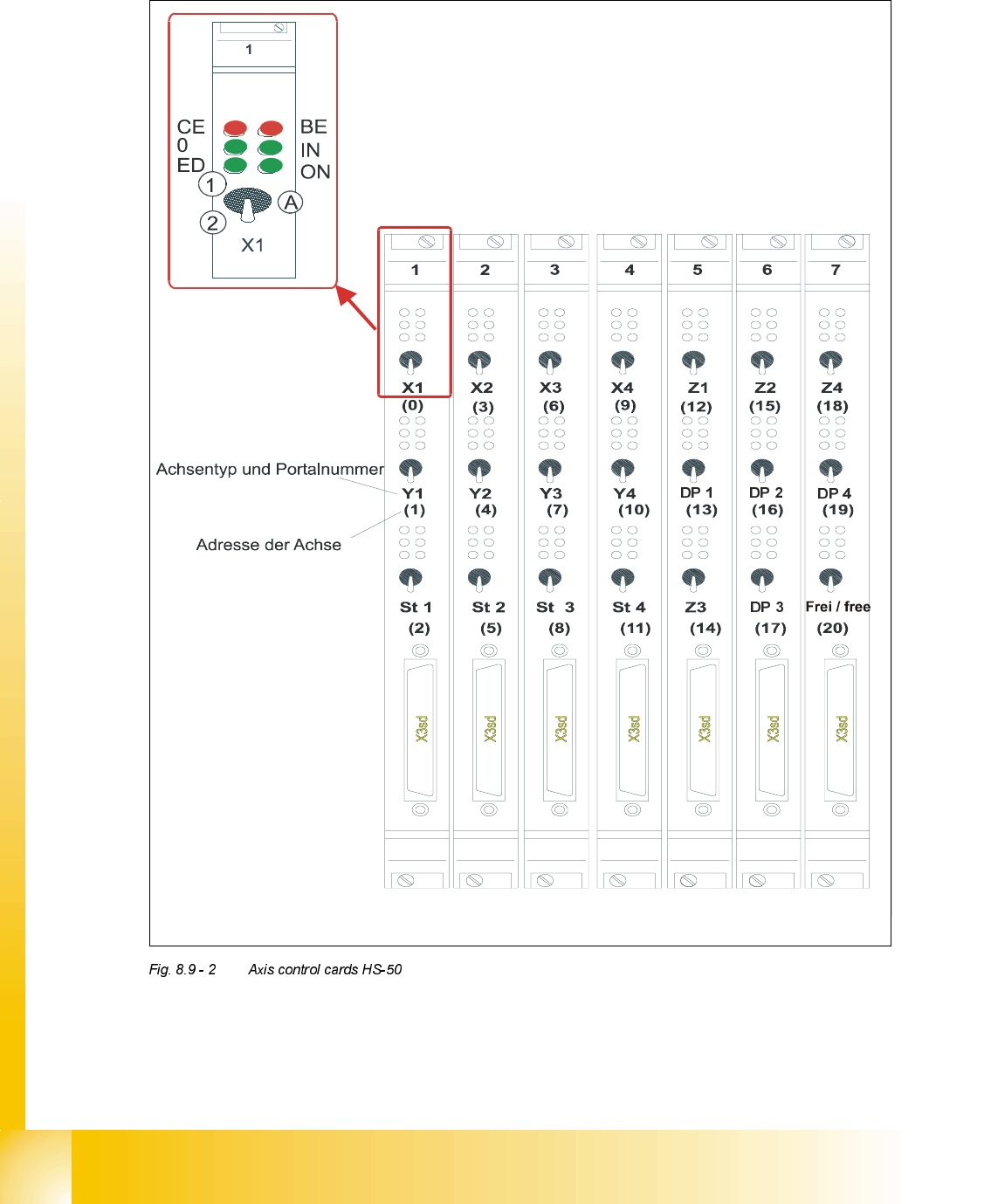
2YHUYLHZRI$[HV&RQWURO&DUGV+6
type of axis and gantry number
adress of axis
CE = Counting error
0 = Zero pulse
ED = End signal
BE = General error, module error
IN = Initialized
ON = Servo ON
(A) "Axis enable" switch
(1) Servo ON
Student Guide HS-50 Advanced II 07/2002 Edition
8 Y-Axis
39
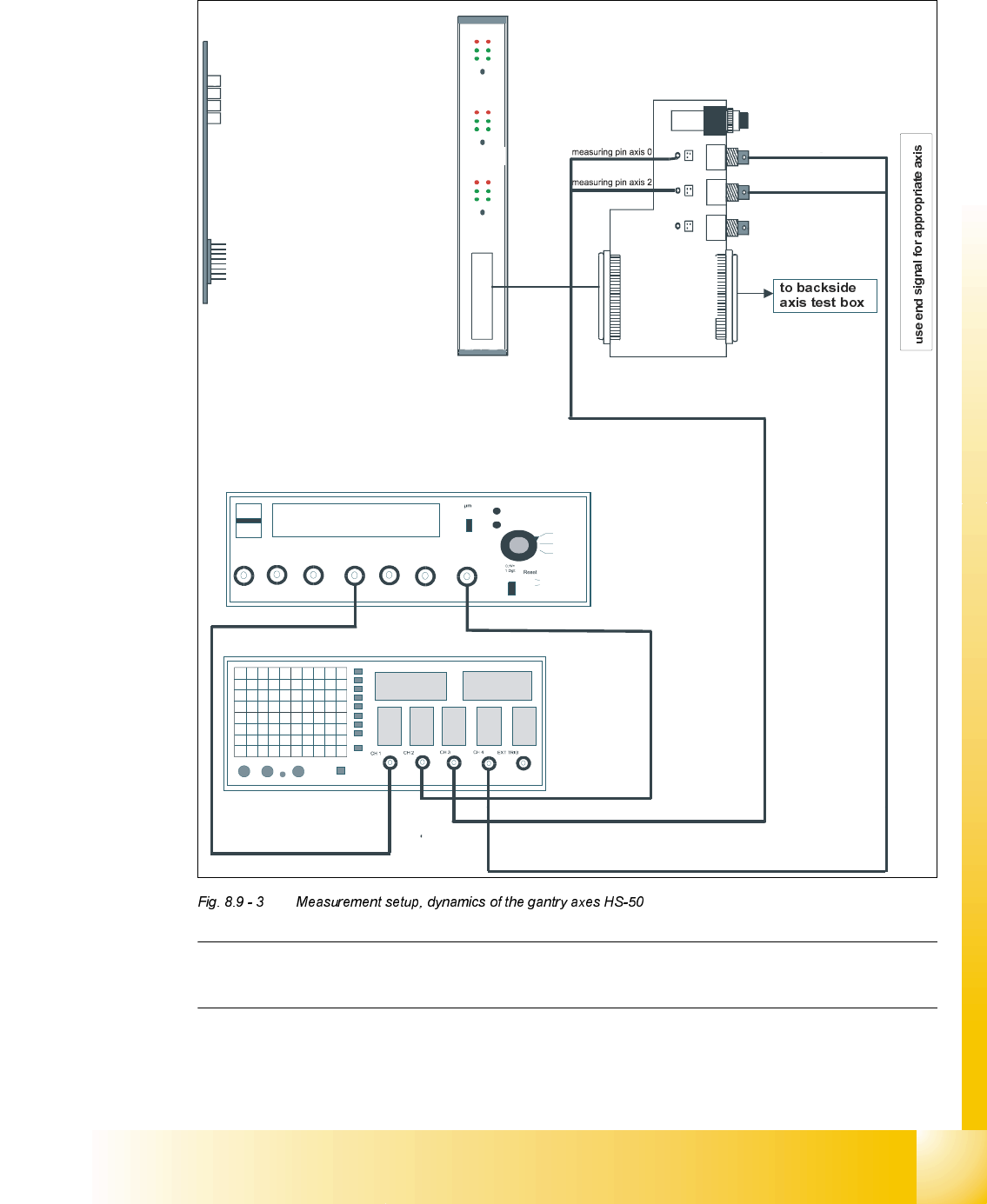
0HDVXUHPHQW6HWXSIRU$[LV$GMXVWPHQWV
NOTE
The current value measured at the adapter board is actual, not (commuted) nominal.
axis 2
Vnominal
ready for operation
enable output stage
effective current limit
error
interface
test adapter
axis test box
i
n
t
e
r
f
a
c
e
a
x
i
s
c
o
n
t
r
o
l
c
a
r
d
i
n
t
e
r
f
a
c
e
a
x
i
s
t
e
s
t
b
o
x
changeover switch pressed down
end signal axis 2
end signal axis 0
d
e
v
i
a
t
i
o
n
o
f
p
o
s
i
t
i
o
n
n
o
m
i
n
a
l
c
u
r
r
e
n
t
e
n
d
s
i
g
n
a
l
track A track B zero pulse Vnom force end signal deviat. of pos.
dgt
zero pulse
end signa
l
axis 0
axis 1
axis 2
OFF
ON
synchronization
axis 0
axis 1
axis 2
07/2002 Edition Student Guide HS-50 Advanced II
8 Y-Axis
40
<$[LV
*HQHUDO3UHSDUDWLRQ
➠ Start SITEST.
➠ Make sure that all friction surfaces are clean.
➠ Prepare the measurement setup for the y-axis. (See Fig. 8.9 - 3).
➠ Perform a head reference run.
➠ Perform a gantry reference run.
NOTE
Use an RC - filter to record the current curve
Measure the end signal on the adapter board "axis test box", with the switch pressed down.
&RQWURO3*DLQ
NOTE
Adjustments of the gantry axes on the servo amplifier are not possible.
Adjustment parameters are preset through board VC10.
This board is positioned on the axis control cards 1, 2, 3 and 4.
Measure the nominal current of the y-axis at the "measuring adapter axis control card, measuring
pin, axis 1".
(Do not connect GND).
6,7(67
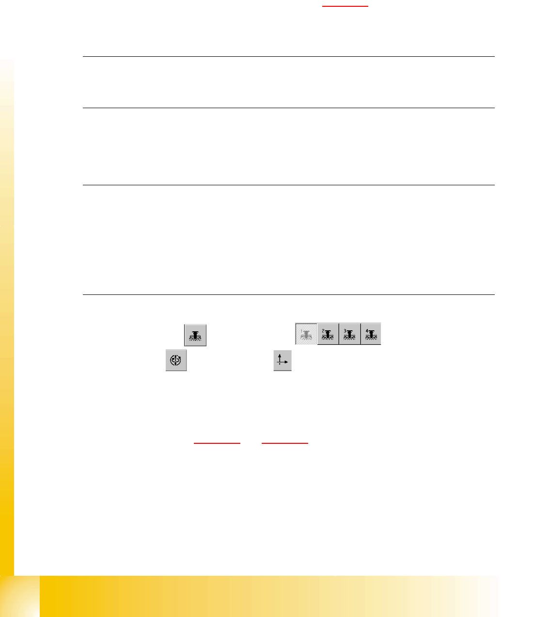
➠ Select "Gantry" ==> ==> "Select gantry" ==>
"Axis functions" ==> "Select y-axis" ==> "Adjust P-gain" ==>
"Select travel range with the help of the ÇÆ arrow buttons".
– If you adjusted the dynamics of the y-axis correctly, each individual signal will be
displayed as shown in Fig. 8.9 - 4
and Fig. 8.9 - 5.
➠ To end the procedure, select "Abort".