HS50_advance_level 2.pdf - 第420页
07/2002 Editio n Student G uide HS -50 Advanc ed II 14 Conveyor System 46 ➠ Make certain that the WUDQVPLVVL RQOHYHU on the p ertinent lifting table motor i s folded down on the liftin g curve ( see Fig . 14.3.5, illust…
Student Guide HS-50 Advanced II 07/2002 Edition
14 Conveyor System
45
,QVWDOOLQJWKH/LPLW6ZLWFKHVIRUWKH:LGWK$GMXVWPHQW6\VWHP
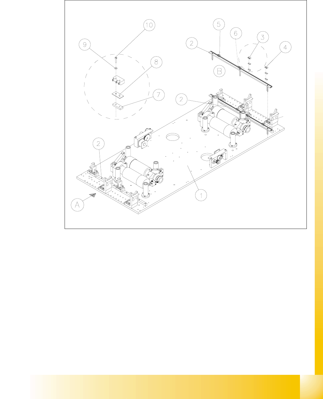
Fig. 14.3.9 Exchanging the Limit Switches for Minimum and Maximum PCB Conveyor Width
Key to Fig. 14.3.9
➠ Mount the new limit switch at the SRVLWLRQPDUNHG.
➠ Resolder the connection wires with FRUUHFWDOORFDWLRQ.
➠ Remove all tools, etc., from the working area of the machine.
A) PCB transport direction B) Set-up of limit switch
1) Mounting plate 2) Profile for limit switch
3) Limit switch maximum width (max.) con-
veyor 1
4) Limit switch minimum width (min.)
conveyor 1
5) Limit switch maximum width (max.) con-
veyor 2
6) Limit switch minimum width (min.)
conveyor 2
7) T-nut for limit switch 8) Spacer for microswitch (limit switch)
9) Disk ) 10) Slotted screw M2 x 12
07/2002 Edition Student Guide HS-50 Advanced II
14 Conveyor System
46
➠ Make certain that the WUDQVPLVVLRQOHYHU on the pertinent lifting table motor is folded down on
the lifting curve (see Fig. 14.3.5, illustration bottom left).
➠ Re-install the lifting table as described in section 14.3.8.2.
➠ Perform the pertinent )LQDOVWHSVLQFOXGLQJ)XQFWLRQ&KHFN (see section 14.4).
➠ Test the limit switch function by actuating the limit switch (manually, if applicable).
Actuating the limit switch the input signal must change from "0" -> "1".
➠ In the conveyor menu, activate the adjustment movement and - with visual inspection of
the position of the movable conveyor side relative to the limit switch - inch toward the limit
switch in small adjustment steps. When actuated, the adjusting movement must be shut
off. The associated input signals must be "1" if the limit switch is actuated.
([FKDQJLQJWKH3UR[LPLW\6ZLWFKIRUWKH3RVLWLRQRIWKH:LGWK$GMXVWPHQW
6\VWHP
For an overview of the layout of the "Proximity switch for position of the width adj. system" at con-
veyor 1 and 2 is available in . 14
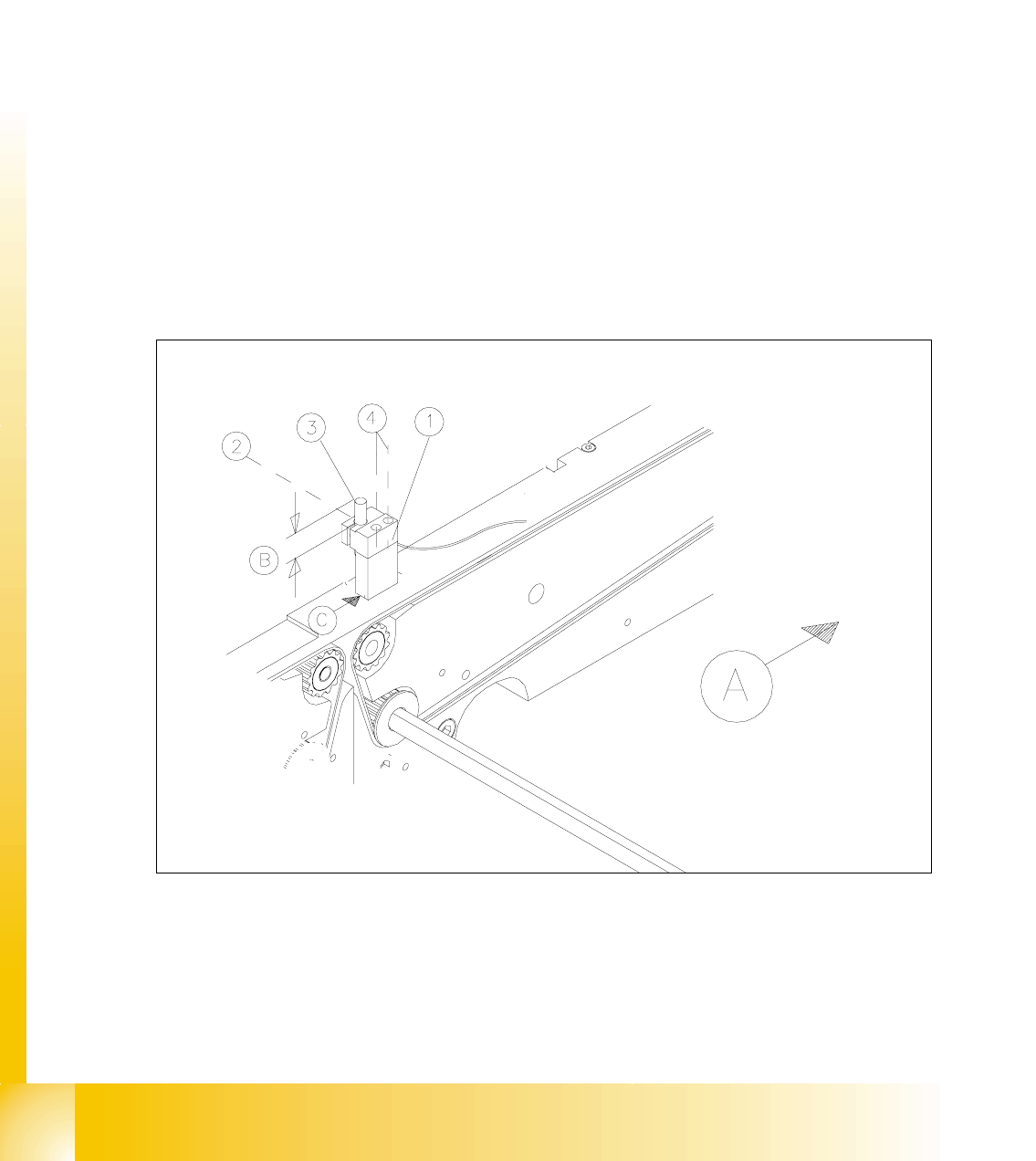
Fig. 14.3.10 Removing the Proximity Switches for the Position of the Movable Conveyor Side

Student Guide HS-50 Advanced II 07/2002 Edition
14 Conveyor System
47
Key to Fig. 14.3.10
5HPRYLQJWKH3UR[LPLW\6ZLWFKHVRIWKH:LGWK$GMXVWPHQW6\VWHP
NOTE:
For the exchange the proximity switch cable must be run on a weaving course as far as the SLIO
module on PCB1 or PCB2, as the case may be (layout: see ). This may be somewhat complicated
due to the routing of cable inside the machine base.
Contact Siemens SMD Service, if you wish, or proceed as described below. 14
➠ Check wether the proximity switch has sustained any mechanical damage which may have
been caused by the JDQWU\. If so, the proximity siwitch was installed incorrectly (too high).
➠ If the proximity switch is XQGDPDJHG, first eliminate other causes such as too great an actua-
toin distance or a poor X13 plug-and-socket connection on the SLIO module (see data below).
➠ Prior to any removal, ascertain the assembly dimension of the XQGDPDJHGproximity switch
(see Fig. 14.3.10 -> %).
➠ Loosen the clamping unit (see Fig. 14.3.10) holding the proximity switch on the mount and pull
out the proximity switch.
➠ Take of the corresponding cable duct cover and FDUHIXOO\remove the cable ties.
➠ Check whether it would be helpful to pull in the cable for the new proximity switch with the aid
of the old one, at least in some area.
➠ Proceed appropriately and FDUHIXOO\run the wiring of the proximity switch on a weaving
course as far as the "SLIO module PCB1" or "...PCB2" (layout: see ).
➠ Disconnect plug-and-socket connection ; (see circuit diagram 6/,2PRGXOH3&%or
3&%).
,QVWDOOLQJWKH3UR[LPLW\6ZLWFKIRU3RVLWLRQRI:LGWK$GMXVWPHQW6\VWHP
➠ Note the different cable lengths for the proximity switches of conveyor 1 and 2.
➠ Run the proximity switch cable from the SLIO module on PCB1 or PCB2 to the proximity switch
mount or vice versa.
➠ Install any new proximity switch in the mount in such a manner that the actuation surface is
pointed XSand the assembly dimension (dimension % -> see Fig. 14.3.10) has been reset.
Clamp the proximity switch in the mount in this position.
A) PCB transport direction B) Assembly dimensions for proximity switch
(measured before removal)
C) Assembly position for retaining bracket
1) Mount for width proximity switch LPH S50 2) 1 hexagonal socket head cap screw
M 3 x 12
3) Proximity switch for position width adj. sys-
tem for conveyor 2 or 1 (conveyor 2 is
shown)
4) Screws for fastening the mount
2 hexagonal socket head cap screws
M 3 x 45