HS50_advance_level 2.pdf - 第67页
Stud ent Gu ide HS-5 0 Adva nced II 07/2 002 Ed ition 3 Power Supply 29 : KDWWRGRRQF RPSOHWLRQRIWK HVHUY LFLQJZ RUN ➠ Fit the power suppl y unit and fix i n place w ith the M8 h exago n socket- head screw…

07/2002 Edition Student Guide HS-50 Advanced II
3 Power Supply
28
5HSODFLQJSDUWV
6DIHW\LQVWUXFWLRQV
DANGER The placement system is supplied with 3 x 400 VAC (or 3 x 204
VAC / 3 x 230 VAC / 3 x 380 VAC / 3 x 415 VAC) ± 5 %, 50/60 Hz main power voltage.
– Consequently, parts of the system carry potentially lethal voltages, even when switched off at
the main switch.
– Incorrect handling of the placement system can therefore result in death or severe injury or
considerable damage to equipment.
– Measurements and repairs must always be carried out by appropriately qualified personnel.
– Always follow the safety instructions in section 2 of this manual.
– Always follow the applicable accident prevention and VDE regulations (particularly DIN EN 60
204 part 1) or the regulations specific to your country.
– Before starting any repairs, switch off at the main switch and disconnect the placement system
from the main power supply.
– Secure the system to prevent it being switched on again. If these instructions are not followed,
it is possible to touch live parts, which could result in death or severe injury.
3UHSDULQJWKHSRZHUVXSSO\XQLWIRUUHSODFLQJSDUWV
➠
End all placement operations on the placement system.
➠ Shut down the Windows NT operating system correctly, otherwise problems may occur when
restarting or data may be lost.
➠ Switch the placement system off at the main switch.
➠ Disconnect the placement system from the main power supply.
➠ Secure the placement system to prevent it being switched on again and put up a sign to indi-
cate that servicing work is being carried out (see section 2, Operational safety).
➠ Open the safety doors with the double-bit key.
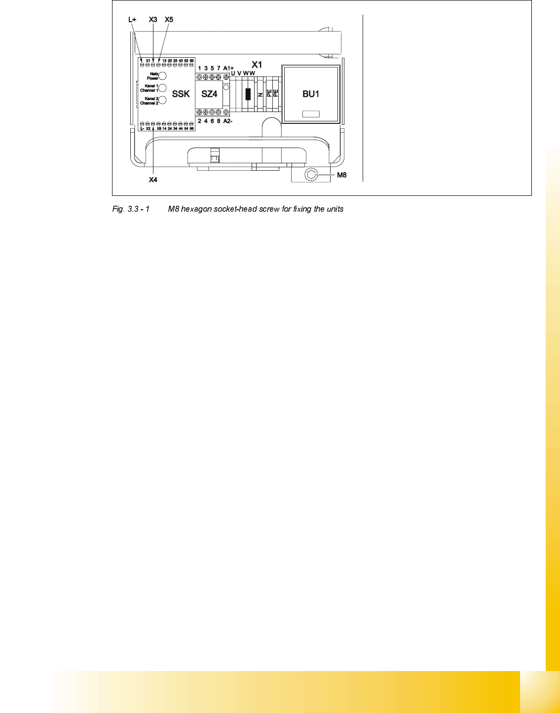
➠ Loosen the M8 hexagon socket-head screw fixing the unit to the underside of the front panel
(see Fig. 3.3 - 1
on page 3 - 29).
Student Guide HS-50 Advanced II 07/2002 Edition
3 Power Supply
29
:KDWWRGRRQFRPSOHWLRQRIWKHVHUYLFLQJZRUN
➠ Fit the power supply unit and fix in place with the M8 hexagon socket-head screw
➠ Make sure that you do not squash the cable when inserting the board
➠ Lock the safety doors
➠ Remove the key and keep in a safe place
5HSODFLQJWKHPDLQVZLWFK6
7RROVDQGHTXLSPHQW
– Set of slotted-head screwdrivers
– Set of DIN 911 Allen keys
– Digital multimeter
– Self-adhesive labels
– HS-50 detailed circuit diagrams
3DUWV
32C4/3-pole/40A main switch, item number 00342395-01
Carefully remove the unit
Make sure that the cable does
not get caught up
Be careful not to damage the
insulation
07/2002 Edition Student Guide HS-50 Advanced II
3 Power Supply
30
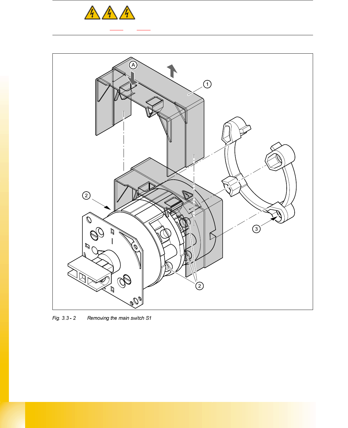
5HPRYLQJWKHPDLQVZLWFK
DANGER Switch off the placement system and disconnect from the power
supply (see sections 3.3.1 and 3.3.2).
➠ Use the screwdriver to bend back the lug (A) of the touch guard (1) slightly and then pull the
guard up and off.
➠ Loosen and remove the cable clamping screws (2) one by one and identify with adhesive la-
bels.
,QSXW 2XWSXW
Cable colour brown black