HS50_advance_level 2.pdf - 第181页
Stud ent Gu ide HS-5 0 Adva nced II 07/2 002 Ed ition 7 X- Axis 23 ,QVW DOOLQJ WKHGH IOHFWLRQ XQLW¶;¶ ➠ Fit the elastomer ic spri ng (item 10 in F ig. 7.5 - 3 ) on th e new de flection unit (item 8 in F ig. …
07/2002 Edition Student Guide HS-50 Advanced II
7 X-Axis
22
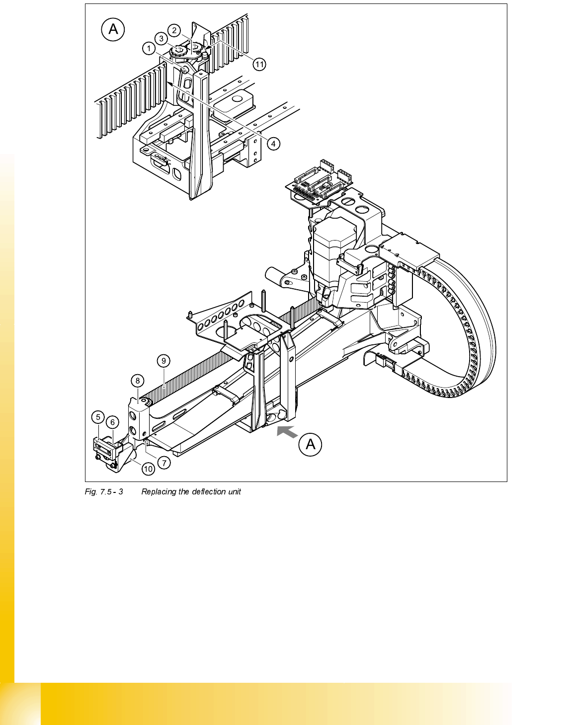
(1) M4 x 35 hexagon socket-head screw (2) Tensioning key
(3) Synchronizing disk, long (4) Opening in tension jack for toothed belt
(5) Y-axis brake, external (6) 2 x M3 x 8 hexagon socket-head screws
(7) 2 x M6 x 10 hexagon socket-head screws (8) Deflection unit - X
(9) Synchroflex toothed belt (10) 25 x 10.5 x 50 elastomeric spring
(11) Locknut
Student Guide HS-50 Advanced II 07/2002 Edition
7 X-Axis
23
,QVWDOOLQJWKHGHIOHFWLRQXQLW¶;
➠ Fit the elastomeric spring (item 10 in Fig. 7.5 - 3) on the new deflection unit (item 8 in Fig.
7.5 - 3
).
➠ Use the two M6 x 10 hexagon socket-head screws (item 7 in Fig. 7.5 - 3) to fix the deflection
unit (item 8 in Fig. 7.5 - 3
) to the gantry.
➠ Align the ’external’ brake (item 5 in Fig. 7.5 - 3) so that it is parallel with the braking surface and
fix to the deflection unit (item 8 in Fig. 7.5 - 3
) using the two M3 x 8 hexagon socket-head
screws.
➠ Place the toothed belt (item 9 in Fig. 7.5 - 3) around the synchronizing disk of the deflection
unit (item 8 in Fig. 7.5 - 3
).
PLEASE NOTE
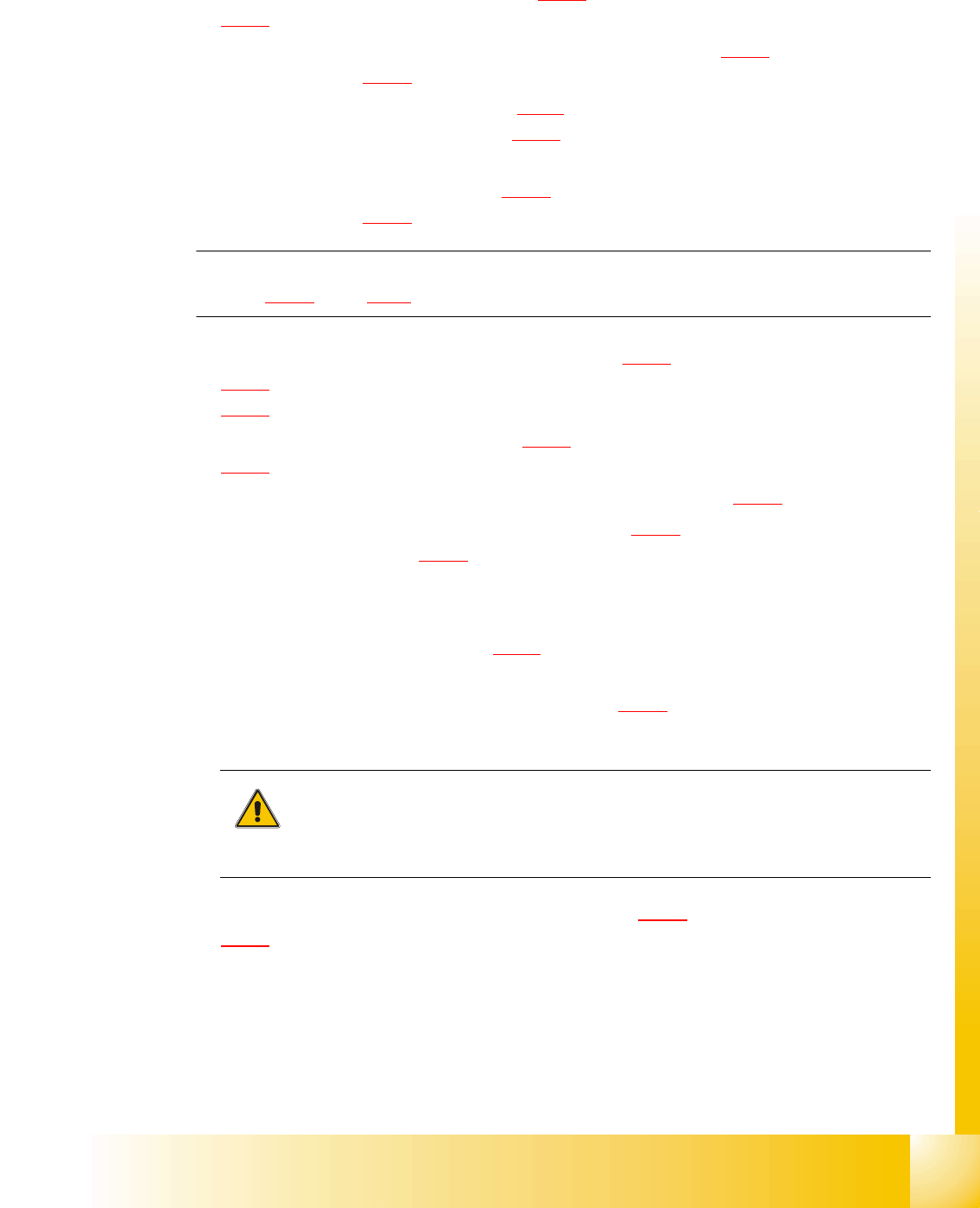
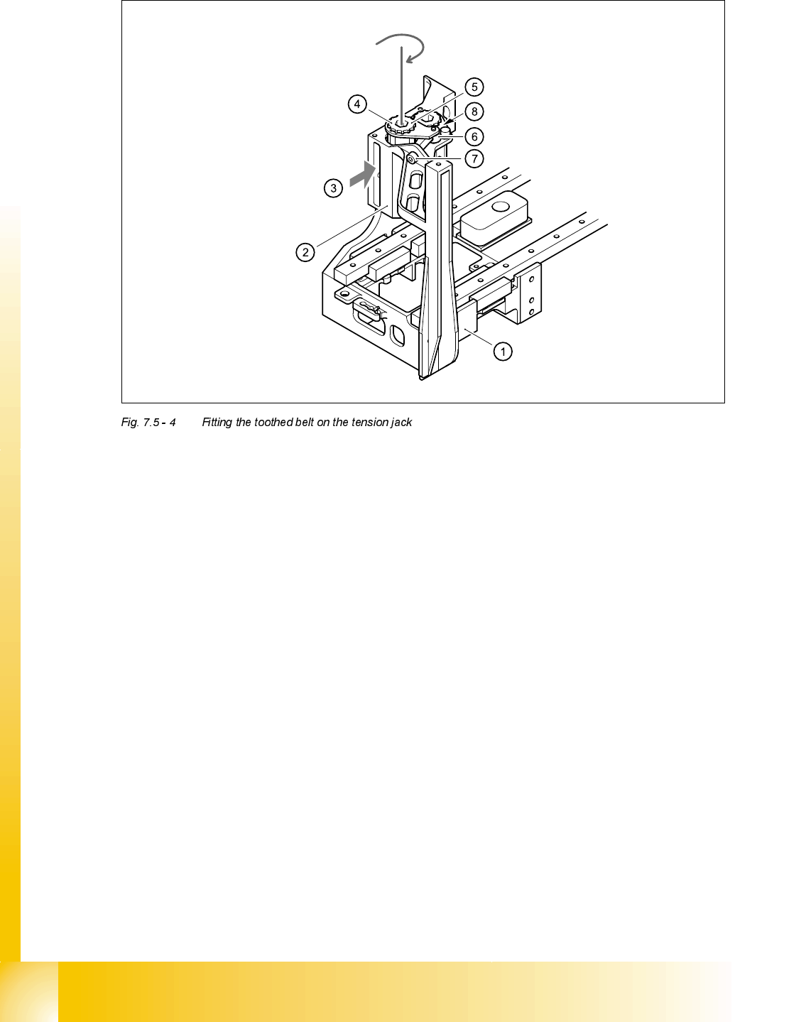
See Fig. 7.5 - 4, page 7 - 24 onward, for the following assembly steps.
➠ Feed the toothed belt into the opening (item 3 in Fig. 7.5 - 4) in the tension jack (item 2 in Fig.
7.5 - 4
) so that it runs approximately 270° around the ’long’ synchronizing disk (item 4 in Fig.
7.5 - 4
).
➠ Place the tensioning key (item 5 in Fig. 7.5 - 4) on the synchronizing disk (item 4 in Fig.
7.5 - 4
).
➠ Use a size 8 Allen key to turn the synchronizing disk (item 4 in Fig. 7.5 - 4) clockwise.
➠ Screw the hexagon socket-head screw (item 7 in Fig. 7.5 - 4) into the threaded hole in the
spacer bolt (item 6 in Fig. 7.5 - 4
) and pre-tension the X-axis toothed belt.
6HWWLQJV
➠ Push the head mount (item 1 in Fig. 7.5 - 4) towards X-axis motor unit as far as the stop on the
elastomeric spring.
➠ Turn the hexagon socket-head screw (item 7 in Fig. 7.5 - 4) to set the belt tension to 53 Hz +
1/-3 Hz.
CAUTION
Do not overstretch the toothed belt when adjusting the belt tension.
➠ Secure the hexagon socket-head screw (item 7 in Fig. 7.5 - 4) with the locknut (item 8 in Fig.
7.5 - 4
).
07/2002 Edition Student Guide HS-50 Advanced II
7 X-Axis
24
(1) Head mount
(2) Tension jack for the toothed belt
(3) Opening for threading the toothed belt
(4) Synchronizing disk, long
(5) Tensioning key
(6) Spacer bolt with M4 threaded hole
(7) M4 x 35 hexagon socket-head screw for tensioning the toothed belt
(8) Locknut