HS50_advance_level 2.pdf - 第58页
07/2002 Editio n Student G uide HS -50 Advanc ed II 3 Power Sup ply 20 7 HU PLQDOS DQHORI WKHS RZHUVX SSO\XQLW The pin a ssignments of the ind ividual pl ugs are s hown in th e detailed circuit d iagrams …

Student Guide HS-50 Advanced II 07/2002 Edition
3 Power Supply
19
Transformer T1 supplies the following voltages on the secondary side:
– 3 x 140 VAC
–3 x 5 VAC
–3 x 24 VAC
–3 x 25 VAC
–3 x 6 VAC
–3 x 38 VAC
–3 x 20 VAC
0HDVXULQJYROWDJHVDWWKHPDLQSRZHUILOWHU=DQGHOHFWURO\WLFFDSDFLWRU&
Z1 Main power filter for 36 A 3-phase systems
E Input terminals of main power filter Z1
A Output terminals of main power filter Z1
C1 33000 µF / 63 V electrolytic capacitor
R1 Discharge resistor
0RGXOH 7HUPLQDO 9ROWDJHV
Main power filter Z1 L1, L2, L3 3 x 204 VAC / 3 x 230 VAC / 3 x 380 VAC
3 x 400 VAC / 3 x 415 VAC
Electrolytic capacitor C1 + / - 52 VDC
R1
C1
Z1
+
-
L1
L2
PE
L3
AE
PE
L3
L2
L1
07/2002 Edition Student Guide HS-50 Advanced II
3 Power Supply
20
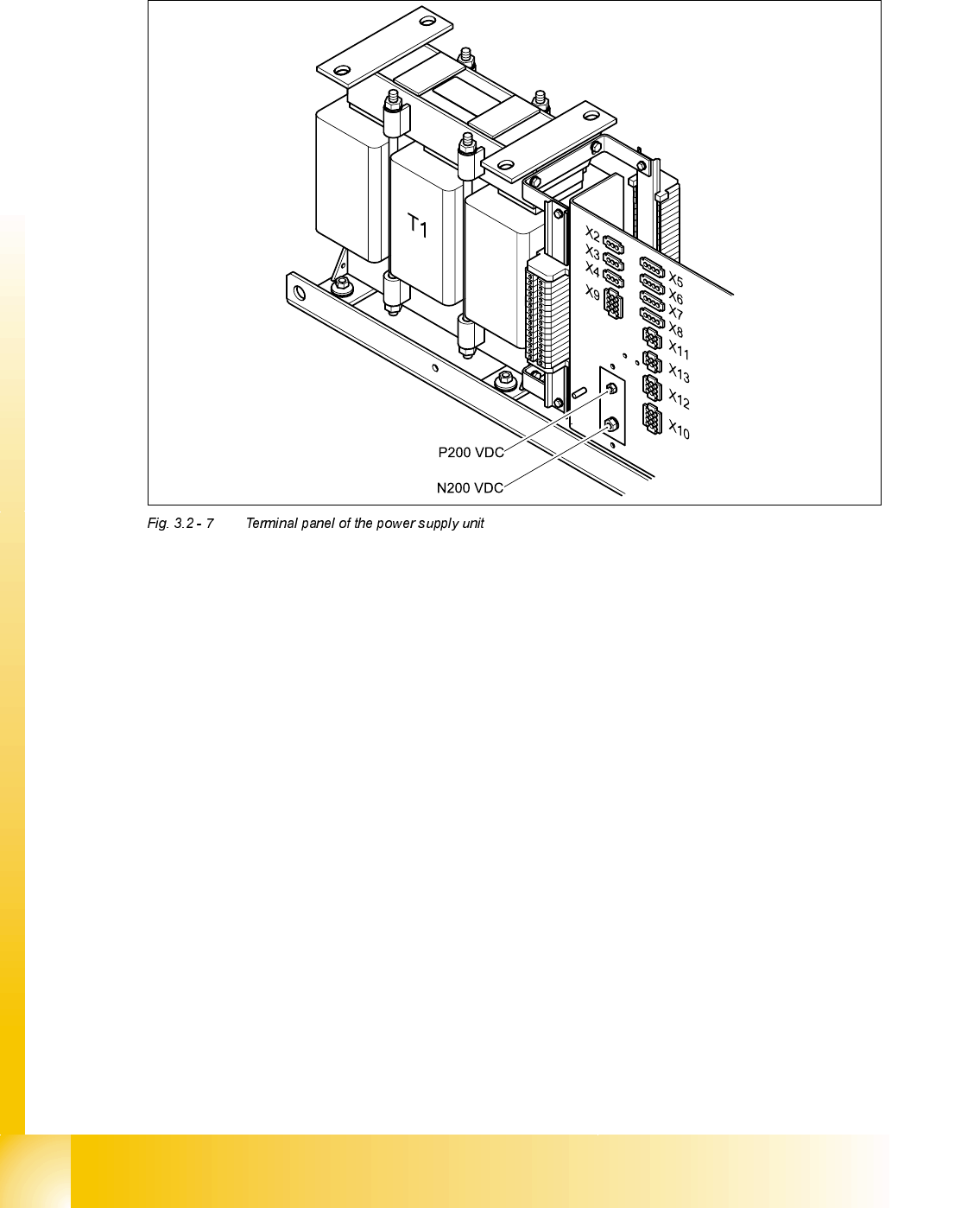
7HUPLQDOSDQHORIWKHSRZHUVXSSO\XQLW
The pin assignments of the individual plugs are shown in the detailed circuit diagrams in section
3 "Circuit diagrams".
T1 11.1 kVA three-phase transformer
P200 V M6 screw terminal (+) for supplying the servo amplifiers of the x/y axes
N200 V M8 screw terminal (-) for supplying the servo amplifiers of the x/y axes
X2 To the PC
X3 To monitor 1
X4 To monitor 2
X5 To lifting table 1, PCB conveyor 1
X6 To lifting table 2, PCB conveyor 1
X7 To lifting table 3, PCB conveyor 2 (option)
X8 To lifting table 4, PCB conveyor 2 (option)
X9 To the servo unit
X10 To the main distribution unit (non-stabilised DC voltages)
X11 To the PCB handling system / lifting table controller
X12 From/to the main distribution unit, (control signals, power supply)
X13 From/to the main distribution unit, (SSK peripherals)
Student Guide HS-50 Advanced II 07/2002 Edition
3 Power Supply
21
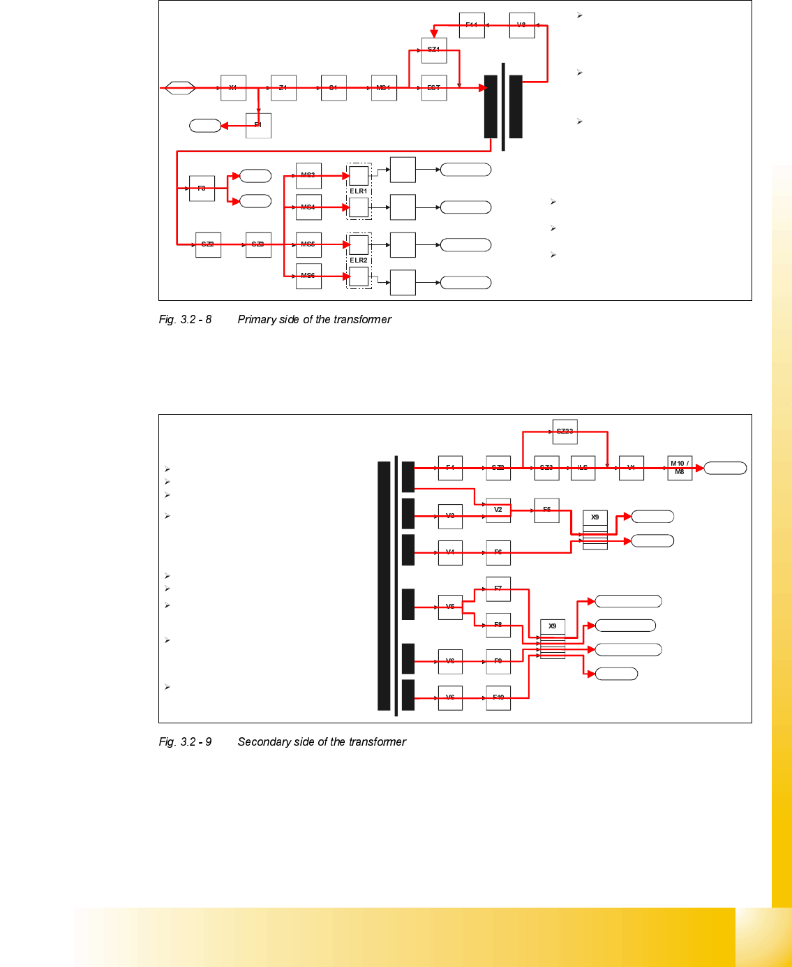
3ULPDU\VLGHRIWKHWUDQVIRUPHU
6HFRQGDU\VLGHRIWKHWUDQVIRUPHU
Bu1
St1
PC
Monitor
Lifting table 1
Lifting table 2
Lifting table 3
Lifting table 4
X5
X8
X7
X6
With the machine switched on by the
main switch (Z1), power ist first supplied
over the inrush current limiter (EST) to
the primary side of the transformer
This causes a small feedback signal on
the secondary side, which activates
contactor SZ1.
With contactor SZ1 activated the inrush
current limiter (EST) is short circuit and
furthermore without function. The
machine is now ready for operation.
On the primary side can be found the power
supply for the service plug (Bu1),
the board net where the station computer and
the two monitor are connected to
and the power supply of the four lifting tavle
motor.
X/Y axes
Star axes
Z/DP axes
Component table 1
Conveyor system
Component table 2
Control unit
W
ith the primary side connected to the main
s
upply voltage bypassing the inrush current
l
imiter the secondary side drives now also:
Supply voltage for the control unit
Supply voltage for the component table logic
Supply voltage for the component table to
drive the feeder modules
The SSK activates then contactor SZ2 and SZ3
by a 24V signal and voltage is supplied over
the inrush current limiter (ILS) to X and Y.
With a short delay also contactor SZ23 is
activated by the 24V to short circuit contactor
SZ3 as well as the inrush current limiter (ILS).
X and Y are now driven by full power.
F
or all the other voltages first the machine
h
as to be started by the
ON button
.
Reduced supply voltage for the Star-axis
With X and Y fully suplied also the Star axis is
now supplied by the main voltage.
Supply voltage to be conveyor motors
Supply voltage for the Z/DP-axis