HS50_advance_level 2.pdf - 第50页
07/2002 Editio n Student G uide HS -50 Advanc ed II 3 Power Sup ply 12 9 ROW DJ HVLQWKH SRZHU VXSSO\XQLW 3UHS DULQJWK HSRZHU VXSSO\XQLWIRUPHDVXUHPHQW The power s upply unit and m ain sw itch a re…
Student Guide HS-50 Advanced II 07/2002 Edition
3 Power Supply
11
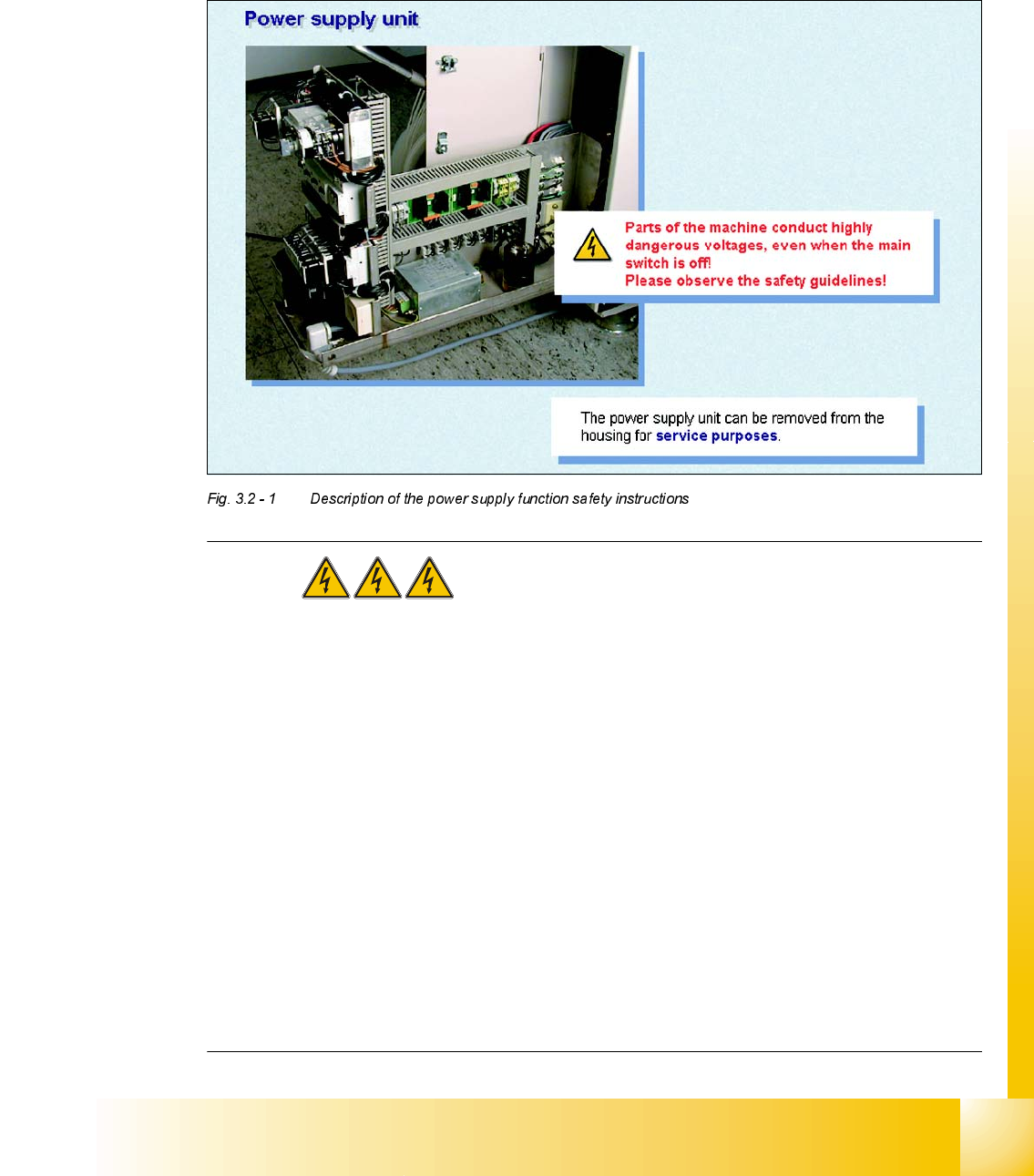
'HVFULSWLRQRIWKHSRZHUVXSSO\IXQFWLRQ
6DIHW\LQVWUXFWLRQV
DANGER The placement system is supplied with 3 x 400 VAC
(3 x 204 VAC / 3 x 230 VAC / 3 x 380 VAC / 3 x 415 VAC) ± 5 %, 50/60 Hz main voltage.
– Consequently, parts of the system carry potentially lethal voltages, even when switched off at
the main switch.
– Incorrect handling of the placement system can therefore result in death or severe injury or
considerable damage to equipment.
– Measurements and repairs must always be carried out by appropriately qualified personnel.
– Always follow the safety instructions in section 2 of this manual.
– Always follow the applicable accident prevention and VDE regulations (particularly DIN EN 60
204 part 1) or the regulations specific to your country.
– Before starting any repairs, switch off at the main switch and disconnect the placement system
from the main power supply.
– Secure the system to prevent it being switched on again. If these instructions are not followed,
it is possible to touch live parts, which could result in death or severe injury.
07/2002 Edition Student Guide HS-50 Advanced II
3 Power Supply
12
9ROWDJHVLQWKHSRZHUVXSSO\XQLW
3UHSDULQJWKHSRZHUVXSSO\XQLWIRUPHDVXUHPHQW
The power supply unit and main switch are located in the machine frame. In front of the unit there
is a set of safety doors which can be opened with the double-bit key.
The unit is fixed to the machine frame using an M8 hexagon socket-head screw.
To measure the power supply, proceed as follows:
➠ Switch the placement system off at the main switch.
➠ Loosen the M8 lock screw on the underside.
➠ Pull the unit out as far as the stop.
WARNING Make sure that the main power cable and supply lines do not be-
come caught up in the placement system, otherwise the insulation will be damaged.
➠ Switch the placement system on at the main switch and start it up.
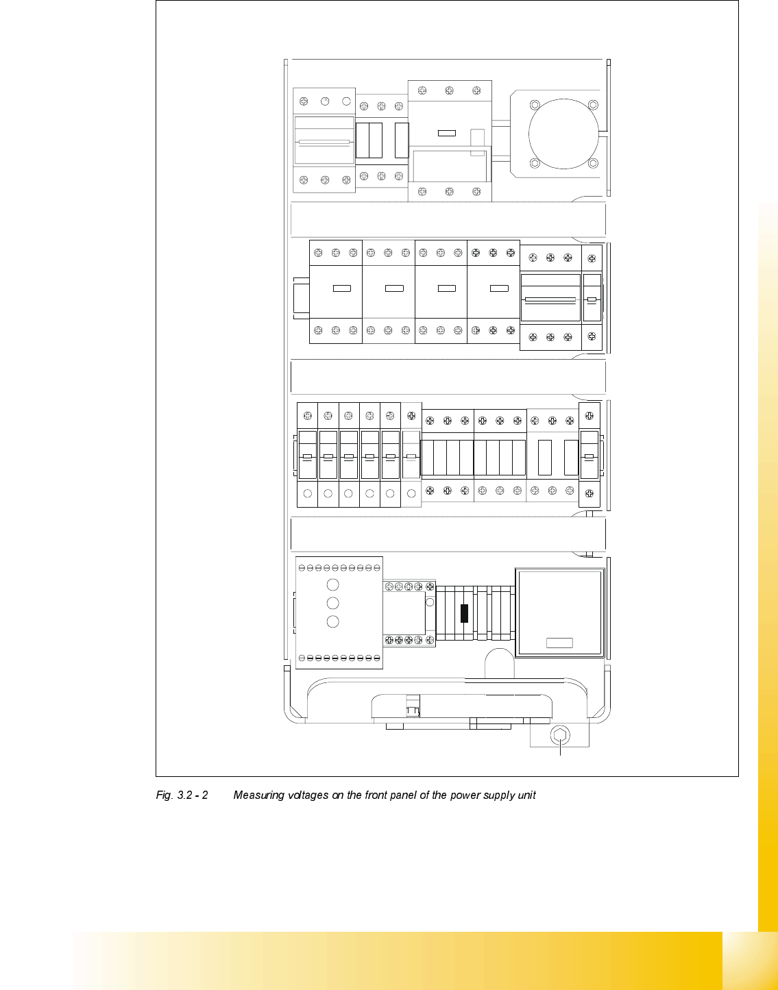
0HDVXULQJYROWDJHVRQWKHIURQWSDQHORIWKHSRZHUVXSSO\XQLW
PLEASE NOTE: The placement system must be started in order to take these measurements.
This means that the protective covers and component flaps must be closed and the component
tables docked. The emergency stop button must be released and the Start button pressed. If this
is not the case, the operating voltages will not be switched through to the servo amplifiers, lifting
tables, etc.
The inputs to the modules all have odd numbers and the outputs have even numbers.
In the case of fuses (F1, etc), the input is always on the underside of the module, whereas with
contactors (SZ1, etc) and motor circuit-breakers (MS1 ...), it is always at the top.
Student Guide HS-50 Advanced II 07/2002 Edition
3 Power Supply
13
246
135
F3
135
246
SZ1
K14
K12
K11
135
246
MS1A
MS1
S1
MS5 MS6MS4MS3
135
2 64 2 64
1 53 31 5
42 6 624
513
F4
426
31 5
F10F9F8F7F6F5
111111
222 222
F1
2
1
SZ2 SZ3
SZ23
246
135135
2462
4
6
1 3
5
K232
K234
K34
K33
K32
K31
K21
K22
K23
K24
SSK
1 375
4268
A1+
A2-
SZ4
X1
VUWW
PE
PE
N
BU1
M8
F11
2
1
54 6614 24 4434X4 X6L-
13L+ X3X1 X5 533323 43 65
Netz
Power
Channel 1
Kanal 1
Channel 2
Kanal 2