HS50_advance_level 2.pdf - 第410页
07/2002 Editio n Student G uide HS -50 Advanc ed II 14 Conveyor System 36 NOTE The lifting tab le motors are prefit ted with cabl e and connec tor (different ar ticle num bers, depe nd- ing on pla cemen t area 1- 4). 14 …
Student Guide HS-50 Advanced II 07/2002 Edition
14 Conveyor System
35
([FKDQJLQJWKH/LIWLQJ7DEOH0RWRUDQGRUWKH6SURFNHW:KHHO
5HPRYLQJWKH/LIWLQJ7DEOH0RWRU6SURFNHW:KHHO
➠ Remove the lifting table as described in section 14.3.8.1.
14
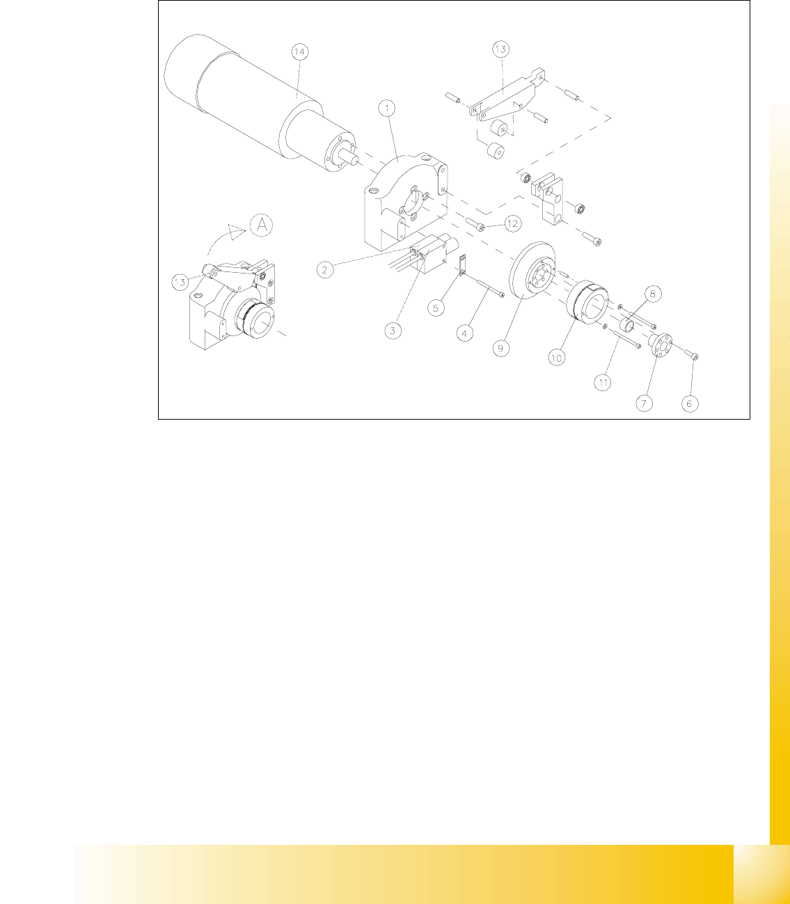
Fig. 14.3.5 Removing the LiftingTable Motor and / or the Lifting Table Proximity Switch
Key to Fig. 14.3.5
A) Fold the transmission lever XS
1) Motor mount 2) Proximity switch "lifting table GRZQ"
3) Proximity switch "lifting table XS 4) Screws fastening the proximity switch :
2 hexagonal socket head cap screws M3 x
30
5) Reinforcement plate for proximity switch 6) Fasteners for clamping flange:
6 hexagonal socket head cap screws
M4x12
7) Clamping flange 8) Annular spring
9) Cam body 10) Sprocket wheel with lead tapes
11) Screws fastening the "sprocket wheel with
lead tapes": 2 hexagonal socket head cap
screws M 3 x 30 with 2 adjusting shims
12) Motor moiunt: 4 hexagonal socket head
cap screws M5 x 12
13) Transmission lever 14) Motor for lifting table 1, 2, 3 or 4

07/2002 Edition Student Guide HS-50 Advanced II
14 Conveyor System
36
NOTE
The lifting table motors are prefitted with cable and connector (different article numbers, depend-
ing on placement area 1-4). 14
➠ Undo and remove the six M4 hexagonal socket head cap screws on the clamping flange (see
Fig. 14.3.5 -> 6). Remove the annular spring under the clamping flange.
➠ Label the allocation of the proximity switch for "lifting table up" and "lifting table down" (see Fig.
14.3.5).
➠ Remove the 2 proximity switches from the motor mount (two M3 hexagonal socket head cap
screws), see Fig. 14.3.5, and take off the "reinforcement plate for proximity switch" in the pro-
cess. Set the proximity switch down on the mounting plate.
➠ Fold XSthe transmission lever (see Fig. 14.3.5 -> 13) on the motor mount.
➠ Undo and remove the 2 hexagonal socket head cap screws on the sprocket wheel (see Fig.
14.3.5 -> 11).
Be careful with the washers underneath and remove the sprocket wheel incl. cam body.
➠ Lift off the cover of the pertinent cable duct which is parallel to the conveyor assembly.
➠ &DUHIXOO\remove the corresponding cable ties.
➠ In the cable duct, disconnect the plug-and-socket connection of the lifting table motor which is
to be removed (X70 / X71 / X72 / X73: see circuit diagram for 3RZHUVXSSO\IRUOLIWLQJWDEOH
PRWRUV.
NOTE:
If you discovered a break in the lifting table cable during a continuity test, the cable to the power
supply unit must be run on a weaving course and disconnected at the corresponding connector
X5 / X 6 / X7 / X8 (see above-mentioned circuit diagram).
You may wish to contact Siemens SMD Service regarding this work. 14
➠ Undo and remove the screws fastening the motor to the motor mount (four M5 hexagonal
socket head cap screws) and pull the lifting table motor out.
,QVWDOOLQJWKH/LIWLQJ7DEOH0RWRU6SURFNHW:KHHO
➠ Install the new lifting table motor and the (new) sprocket weel in the reverse order to that de-
scribed for the removal (see section 14.3.9.1).
The pin in the sprocket wheel secures the VSURFNHWZKHHOLQWKHFRUUHFWSRVLWLRQ.
CAUTION O
When several lifting table motors are being removed/installed at the same time, check that the
plug-and-socket connections in the cable duct are allocated correctly (see the circuit diagram
:Power supply for lifting table motors 1 - 4"). The strain on the plug-and-socket connections must
be relieved after the cable ties are attached. 14

Student Guide HS-50 Advanced II 07/2002 Edition
14 Conveyor System
37
➠ Remove all tools, etc., form the working area of the machine.
➠ Fold the transmission lever on the lifting table motor GRZQ (see Fig. 14.3.5: illustration bottom
left).
➠ Install the lifting table plate as described in section 14.3.8.2.
➠ Carry out the pertinent )LQDOVWHSVLQFOXGLQJWKHIXQFWLRQFKHFN.
([FKDQJLQJWKH3UR[LPLW\6ZLWFKIRU/LIWLQJ7DEOH8S3UR[LPLW\6ZLWFK
IRU/LIWLQJ7DEOHGRZQ
5HPRYLQJWKH3UR[LPLW\6ZLWFKIRU/LIWLQJ7DEOH8SDQGRU'RZQ
➠ Remove the lifting table as described in section 14.3.8.1.
➠ Remove the faulty proximity switch for "Lifting table down" or "Lifting table up" from the motor
mount as described in section 14.3.9.1.
– If both proximity switches are faulty, label the allocation "up" / "down" before removing them.
➠ Unplug the cableRQthe lifting table proximity switch which is to be removed (X5 / X6; X8/ X9
-> see circuit diagram of6/,2PRGXOHRQ3&%FRQYH\RU or
RQ3&%FRQYH\RU. See NOTE below.
NOTE:
If you have discovered a break in the proximity switch cable during a continuity check, the prox-
imity switch cable must be run on a weaving course as far as the SLIO module (layout: see ) and
unplugged at the corresponding connector of the SLIO module on conveyor 1 or 2 (X1 / X2, X4 /
X 5: see above-mentioned circuit diagrams). This may be somewhat complicated depending on
the routing of cables inside the machine base.
You may wish to contact Siemens SMD Service regarding this work. 14
,QVWDOOLQJWKH3UR[LPLW\6ZLWFKIRU/LIWLQJ7DEOH8SDQGRU'RZQ
➠ Use the two m3 hexagonal socket head cap screws on the motor mount to fasten the new prox-
imity switch(es), to the motor mount with the correct allocation "up" / "down" (see Fig. 14.3.5).
➠ Mount the plug-and-socket connector on the new proximity switch(es).
➠ Remove all tools, etc., from the working area of the machine.
➠ Move the transmission lever on the lifting table motor down to the lifting curve (see Fig. 14.3.5,
illustration bottom left).
➠ Re-install the lifting table as described in section 14.3.8.2.
➠ Using the SITEST program, conduct a function check of the proximity switches.