HS50_advance_level 2.pdf - 第151页
Stud ent Gu ide HS-5 0 Adva nced II 07/2 002 Ed ition 6 Control & Co mmunicatio n 21 0RWRUFXUUHQW FRQWURO ORRSDQGF RPSDUDWRU The outp ut of the RPM contr oller produce s the set point va lue for motor c urrent…
07/2002 Edition Student Guide HS-50 Advanced II
6 Control & Communication
20
%DOODVW&LUFXLW
The kinetic energy, stored in the motor and load is fed back into the power supply unit during brak-
ing by the servo amplifier. In the case of large moments of inertia the energy take-up of the filter
capacitors in the power supply units is inadequate, and the servo amplifier would be isolated dur-
ing breaking. To prevent this from happening the ballast circuit absorbs the remaining energy and
ensures correct braking via the servo amplifier.
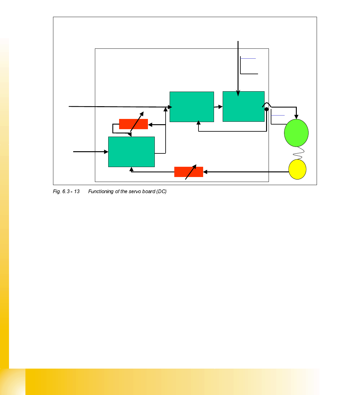
)XQFWLRQLQJRIWKH6HUYR%RDUG'&
The servo amplifier is used as final controlling element for the actual speed of the axis drive. It
attempts to adjust the motor voltage so that the system deviation between specified setpoint
speed and tacho-generator feedback is as small as possible. For force control a power controller
is available. The power controller (current sensor mode) is only used with the Z-axis, when com-
ponents are being mounted with higher placement force (the minimum z-axis force is defined by
the spring loaded sleeve).
7KH6HUYRFDUGFRQVLVWVRI530&RPSDUDWRUDQG&RQWUROOHU
This system compares the setpoint speed requirement, given by the axis controller (V nom) with
the actual motor speed given by the tacho generator fixed to the motor shaft. The tacho generator
generates a voltage, which is directly proportional to speed; the faster the motor turns the higher
the generated voltage. The amount of tacho voltage feed back into the system can be controlled
by adjustment of the tacho potentiometer on the servo card. Therefore motor speed can be directly
affected by adjustment of the tacho potentiometer. The P-gain of this RPM-controller is adjusted
to control the positioning quality of the axis. Therefore you check can the positioning quality ac-
cording to the size and the amount of overshoots after crossing the target position for the first time.
Basic DC-Servo Card Function
Analogue
control signals
from Axis card.
RPM Controller
with Comparator
Motor Control
System
Motor Current
control loop
with Comparator
Controlled
voltage to
motor.
V Nom
V Force
Tacho Adjustment
P Gain Adjustment
Motor
Tacho
Power supply
Student Guide HS-50 Advanced II 07/2002 Edition
6 Control & Communication
21
0RWRUFXUUHQWFRQWUROORRSDQGFRPSDUDWRU
The output of the RPM controller produces the set point value for motor current controller loop.
The output of the servo system is fed back current controller loop in order to control the limit of the
motor current. An additional element is the input of the force voltage from the axis controller, which
is used to provide the current limit for the axis movement. An additional element for the X & Y axis
is the (additional) speed signal given by the force input of the servo amplifier to boost the accel-
eration and deceleration. Fixed value resistors limit the maximum motor current and they are
specified by the motor data.
0RWRUFRQWUROV\VWHP3RZHUVWDJH
Here the motor current is controlled to directly affect the motor speed. The output signal of the
current controller is amplified here and fed to the power semiconductors to generate the motor
current. (See Power supply).
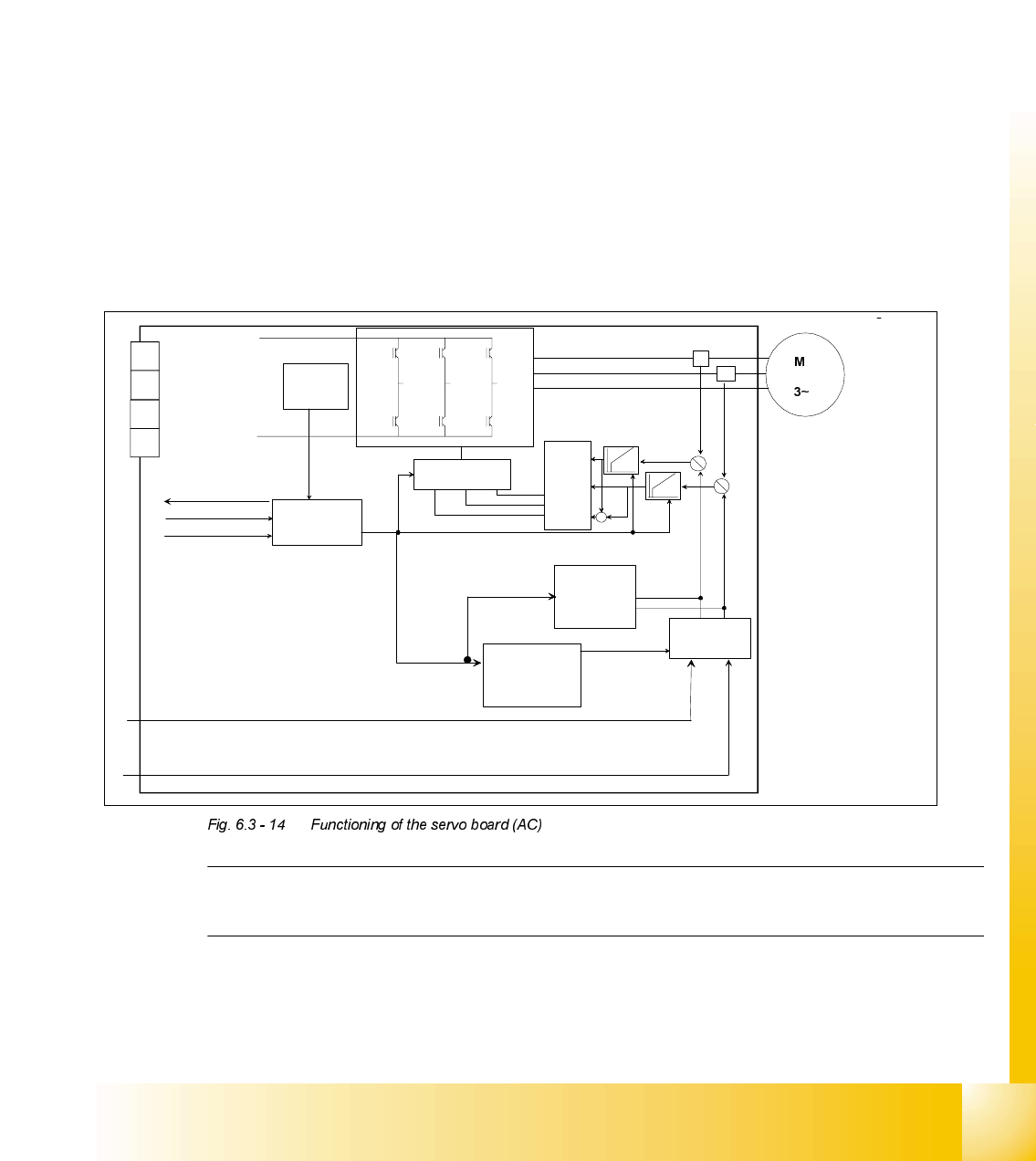
)XQFWLRQLQJRIWKH6HUYR%RDUG$&
NOTE
The AC Servo card produces the 3 phase AC voltage from the DC voltage inputted into the card.
The third
current signal
is generated on
servo board:
0 - I
L1
- I
L3
= I
L2
Inverter
+
-
+
-
current controlling signal input I
u
/ I
w
current pulse
limiter
I RMS current
limiter
current
commutation
controller
pulse-
witdth-
modulation
over- under
voltage
over current
power stage
operational
controlling
and error logic
2 current controller
Enable start enable
controlling dynamic brake
power supply
readyt
Servo ON
I RMS
error
fatal
error
Inverter

07/2002 Edition Student Guide HS-50 Advanced II
6 Control & Communication
22
0RWRUFXUUHQWFRQWUROORRSDQGFRPSDUDWRU
The output of the Axis controller produces the Nominal value (I
nom_U
/ I
nom _W
) for motor current
controller loop. The output of the servo system is fed back current controller loop in order to control
the limit of the motor current. Fixed value resistors limit the maximum motor current and they are
specified by the motor data. Additionally the I2t current control loop checked the nominal value (I
nom_U
/ I
nom_W
) which are coming from the Axis controller.
The nominal value (I
nom_U
/ I
nom _W
) put themselves together as follows (axes controller):
theoretical value which results from calculation of the speed profil.
Deviation of the speed controller.
Deviation of the velocity control unit.
Deviation of the position controller.
Deviation is formed from the actual signals (Track signals A and B) and the target position.
0RWRUFRQWUROV\VWHP3RZHUVWDJH
Here the motor current is controlled to directly affect the motor speed. The output signal of the
current controller is amplified here and fee to the 3 phase power semiconductors to generate the
AC-motor current. The current controller is a PI controller and performs the coarse positioning of
the axis, there he through its integration part most rapid to deviations may react control.