HS50_advance_level 2.pdf - 第91页
Stud ent Gu ide HS-5 0 Adva nced II 07/2 002 Ed ition 3 Power Supply 53 CAUTION Ensur e that th e cables do not bec ome trapp ed, oth erwise th e ins ulation wi ll be damaged. ➠ Fix the fi xing bar in plac e. ➠ Complet…
07/2002 Edition Student Guide HS-50 Advanced II
3 Power Supply
52
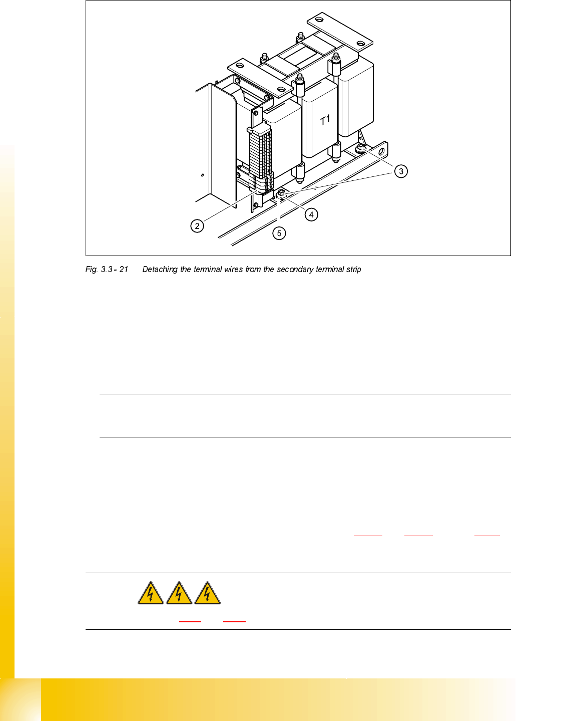
)LWWLQJWKHWUDQVIRUPHU7
➠ Check that there are four rubber washers and four plain washers on the screw bolts on the bot-
tom of the unit.
➠ Place the transformer in the power supply unit.
➠ Place the four rubber washers (5) on the screw bolts.
PLEASE NOTE:
These rubber washers are important because they absorb noise and vibration.
➠ Attach the four plain washers (4).
➠ Use the four M8 hexagon nuts to fix the transformer T1 in place.
➠ Connect the terminal wires to the primary and secondary terminals.
➠ Switch the placement system on and use the digital voltmeter to measure the voltages on the
primary and secondary sides of the transformer (see Fig. 3.2 - 4
and 3.2 - 5 on page 3 - 18.
DANGER Switch off the placement system and disconnect from the power
supply (see sections 3.3.1 and 3.3.2).
➠ Push the power supply unit so that it is half-way in the placement system.
Student Guide HS-50 Advanced II 07/2002 Edition
3 Power Supply
53
CAUTION
Ensure that the cables do not become trapped, otherwise the insulation will be damaged.
➠ Fix the fixing bar in place.
➠ Complete the servicing work as described in 3.3.3 on page 3 - 29.
5HSODFLQJUHFWLILHU9DQG9
7RROVDQGHTXLSPHQW
– Set of slotted-head screwdrivers
– Open-ended spanner or socket spanner, size 8
– Self-adhesive labels
– Heat transfer compound
– Digital multimeter
– HS-50 detailed circuit diagrams
3DUWV
V1, V7 rectifier S101-B6U-160-08, item number 00341246-01
5HPRYLQJWKHUHFWLILHU
DANGER Switch off the placement system and disconnect from the power
supply (see sections 3.3.1 and 3.3.2).
07/2002 Edition Student Guide HS-50 Advanced II
3 Power Supply
54
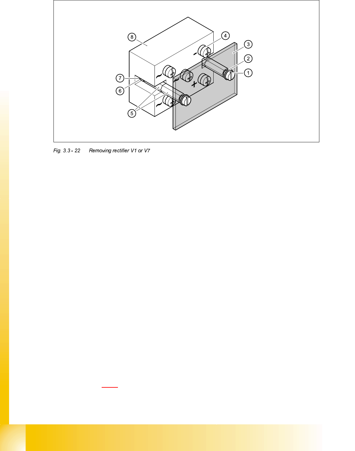
➠ Loosen the M5 fillister head screws (1).
➠ Remove the retaining rings (2).
➠ Remove the perspex cover (3)
➠ Loosen the terminal wire screw connections (4) one by one and identify with self-adhesive la-
bels.
➠ Loosen the hexagon screw bolts (5).
➠ Loosen the M5 nuts (6).
➠ Remove the lock washer (7).
➠ Remove the rectifier (8).
➠ Remove residue of heat transfer compound from the surfaces of the unit.
)LWWLQJUHFWLILHU9DQG9
➠ Apply heat transfer compound to the "metal side" of the rectifier.
➠ Fit the rectifier (8).
➠ Fit the lock washer (7) and fix to the rectifier with an M5 hexagon nut (6).
➠ Attach the hexagon screw bolts (5).
➠ Connect the terminal wires (4) (ensure that the polarity is correct).
➠ Switch the placement system on and start it up.
➠ Use the digital voltmeter to measure the voltages shown in the "Voltages at rectifiers V1 - V8"
table on page 3 - 16
.