HS50_advance_level 2.pdf - 第208页
07/2002 Editio n Student G uide HS -50 Advanc ed II 7 X-Axis 50 NOTE If you adj usted the r ead he ad correc tly , t he foll owing illus tration will appe ar on the s creen of the oscill osco pe: .(< (1) No spu …

Student Guide HS-50 Advanced II 07/2002 Edition
7 X-Axis
49
➠ Set the track signal tester to position "Signal output".
➠ Manually, move the appropriate axis (x = head / y = gantry) back and forth.
CH 1
signal output zero pulse DC 0.5 V/ DIV
2.5V norm
pre- trig. 50%
20 ms
07/2002 Edition Student Guide HS-50 Advanced II
7 X-Axis
50
NOTE
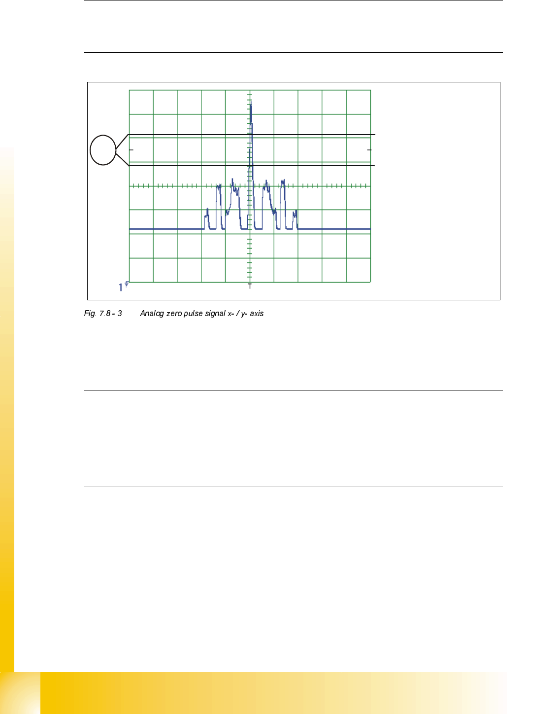
If you adjusted the read head correctly, the following illustration will appear on the screen of the
oscilloscope:
.(<
(1) No spurious peaks are allowed in this measuring range.
NOTE
Check the analog signal of the zero pulse, to ascertain that the zero pulse is discerned correctly.
If the zero pulse is not discerned correctly, the axis will reference to a spurious peak.
Placement offsets will be the result.
The pulse width of the analog zero pulse is dependent on the speed at which the axis is
traversed.
CH1
Student Guide HS-50 Advanced II 07/2002 Edition
7 X-Axis
51
'LJLWDO7UDFN6LJQDOVRI*DQWU\$[HV
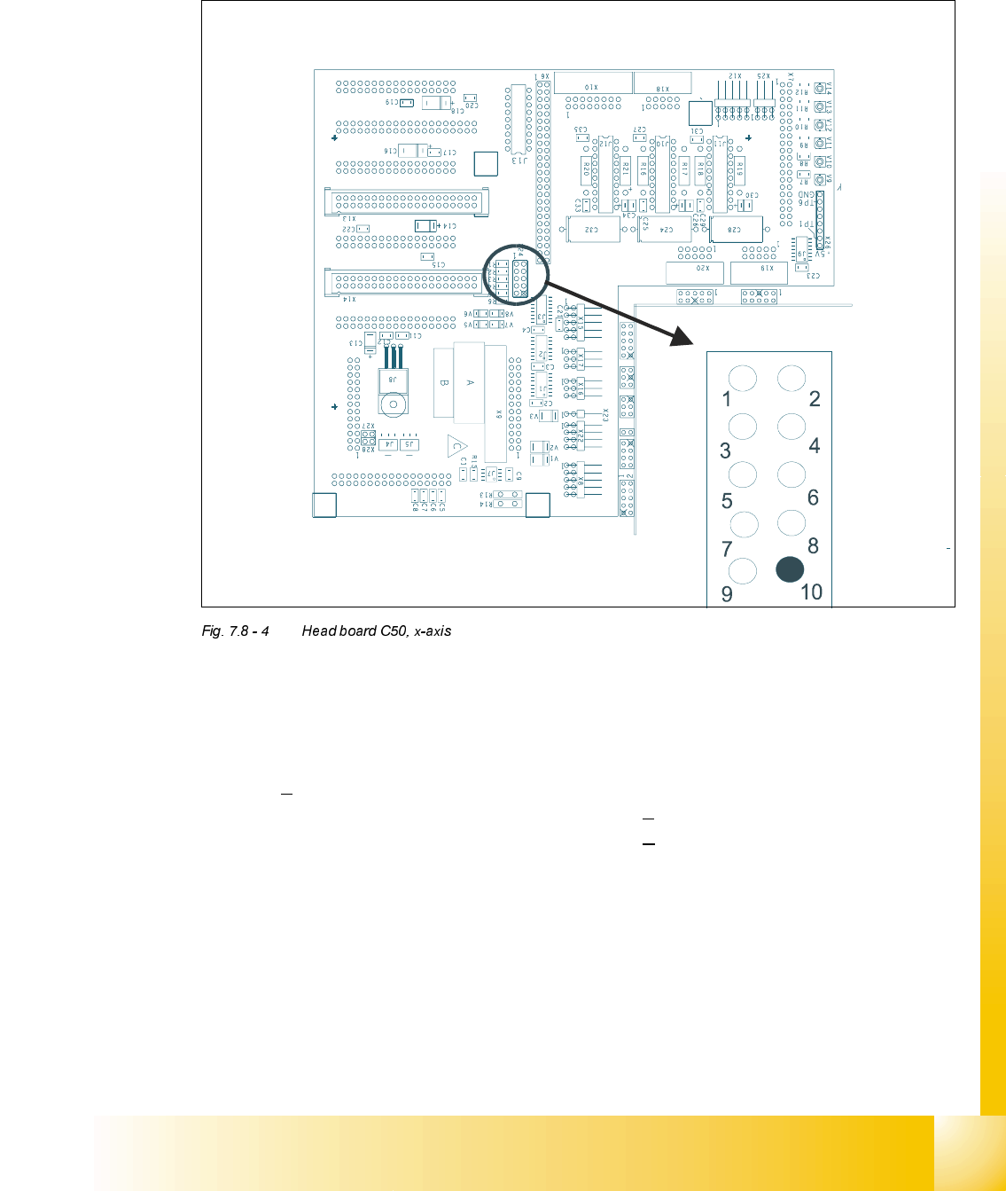
0HDVXUHPHQWRIGLJLWDO7UDFN6LJQDOVRI;$[HV&RQQHFWRU;RQ+HDG%RDUG&
.(<
; = x-axis
Pin configuration
;
1. Ground 2. Track A
3. Track A
4. Ground
5. Track B 6. Track B
7. Track N 8. Track N
9. -4V 10.removed