HS50_advance_level 2.pdf - 第283页
Stud ent Gu ide HS-5 0 Adva nced II 07/2 002 Ed ition 9 Z-Axis 23

07/2002 Edition Student Guide HS-50 Advanced II
9 Z-Axis
22
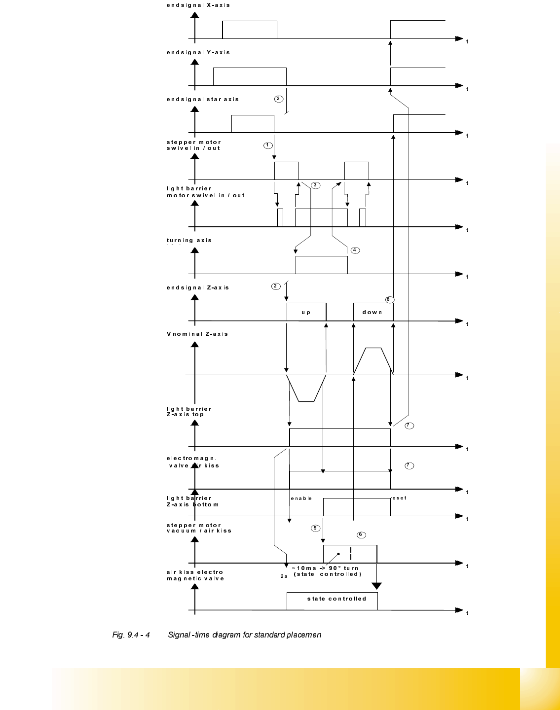
6WDQGDUGSODFHPHQWF\FOH
1) The end signal star axis starts the swivel - in function at the DP-station.
2) The last end signal of the X- Y- or Star axis start the downward movement of the Z-axis and
open the air blow valve. (A vacuum check before the placement will be performed before the Z-
axis movement)
2a.The LB-top-Signal activate the airkiss-electro magnet valve.
3) The end signal of the swivel in - function starts the DP-axis for an segment with component to
turn it to the placement angle (inclusive all corrections).
4) The end signal of the DP-axis starts the swivel - out function.
5) The end signal Z-axis down (LB- signal) starts the valve drive vacuum- /air kiss valve. The motor
rotates by 180° to connect the segment to the air kiss channel and give way for the next Star-axis
movement.
6) The 90 degree movement signal from stepper motor execute an airkiss check and starts the Z-
axis upwards. The stepper motor continue movement untill 180 degree.
7) The light barrier Z-axis on top reset the LB-signal Z-axis at the bottom and starts the gantry
axes.
8) The endsignal Z-axis in top position starts the Star axis.
Student Guide HS-50 Advanced II 07/2002 Edition
9 Z-Axis
23
07/2002 Edition Student Guide HS-50 Advanced II
9 Z-Axis
24
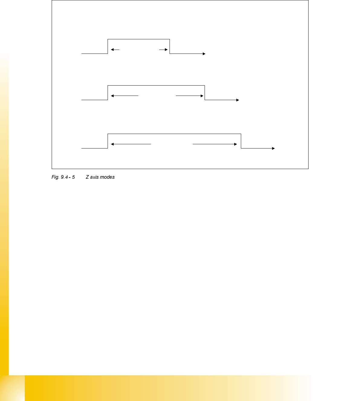
=$[LV0RGHV
'LIIHUHQW=0RGHV
The Z-axis can be controlled with 3 different modes. These are shown above and a description of
each is detailed below.
/LJKW%DUULHU0RGH
This mode is used for all component pick-ups and for the majority of component placements. As
a default components are placed with a force of 1 or 2 as defined in the GF editor at the line com-
puter. When these values are used the light barrier mode is used when the component is placed.
This mode relies on the bottom light barrier reacting to the spring in the segment sleeve being
compressed and as a result the collar on the sleeve rising. The bottom light barrier will be acti-
vated by this movement of the collar and switch to a high status. This signal is then transmitted by
the CAN BUS to the machine controller and the ’End Signal’ is given.
Light Barrier Mode
Current Sensor Mode
Stand – Still
Check
The effect of ‘End Signal’ time with different Z modes.
Approx 30 ms
Approx 50 ms
Approx 70 ms