HS50_advance_level 2.pdf - 第393页
Stud ent Gu ide HS-5 0 Adva nced II 07/2 002 Ed ition 14 Conve yor System 19 5HSO DFLQJVS DUHS DUW V CA UTIO N O Customer s are no t to und o any sc rews se cure d with loc tite. 14 NOTE Use the following diagra…
07/2002 Edition Student Guide HS-50 Advanced II
14 Conveyor System
18
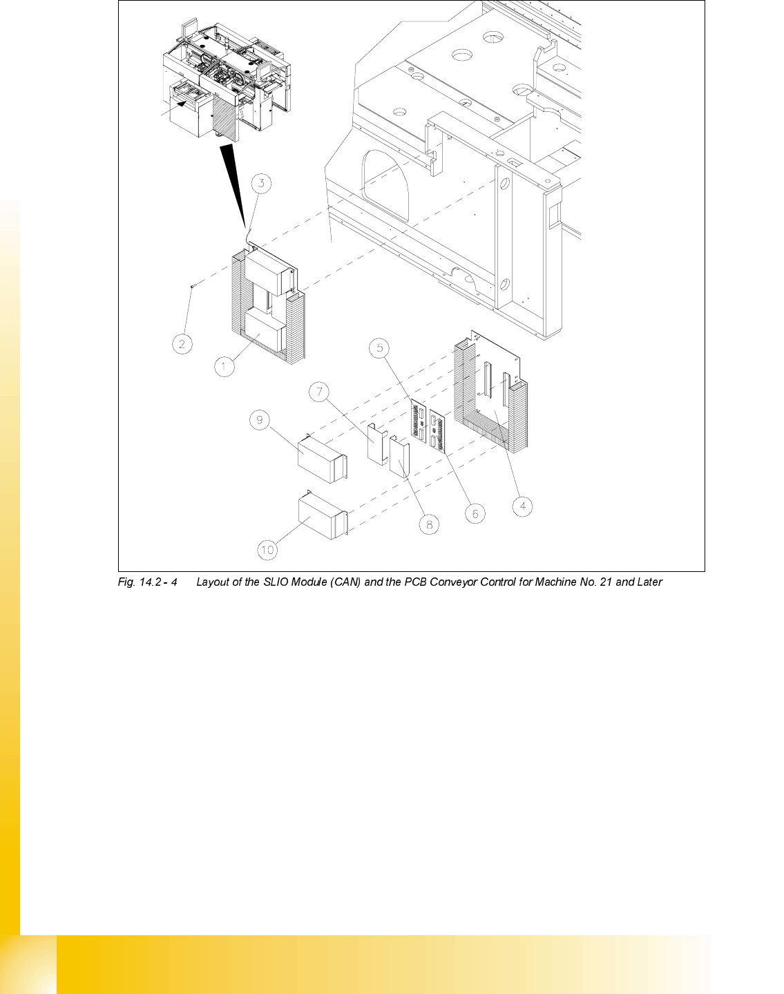
Key to
1) Mounting plate for PCB conveyor HS50,
dual conveyor (= complete)
2) Fastener for mounting plate
hexagonal socket head cap screw M5 x 12
3) Ground wire for mounting plate machine 4) Mounting base, mounting plate for PCB con-
veyor HS50
5) CAN input/output module (SLIO module),
conveyor section (mounts on top-hat rail)
6) CAN input/output module (SLIO module),
Conveyor section (mounts on top-hat rail)
7) Cover for SLIO LPH 50 (conveyor1) 8) Cover for SLIO LPH 50 (conveyor 2)
9) Conveyor control, conveyor section 10) Conveyor control, conveyor section

Student Guide HS-50 Advanced II 07/2002 Edition
14 Conveyor System
19
5HSODFLQJVSDUHSDUWV
CAUTION O
Customers are not to undo any screws secured with loctite. 14
NOTE
Use the following diagrams from the current circuit diagram folder whenever detaching/con-
necting the electrical connections/connectors of the control elements (limit switches, sonar prox-
imity switches and inductive proximity switches) and the motors (drives for lifting table, conveyor
and width adjustment system:
- "SLIO module on PCB1" or "-.... on PCB2"
- "Conveyor module on PCB1 and/or "-.... P2"
- "Power supply for lifting table motor 1-4 (conveyor 1 / 2)"
Before
disassembling a motor, control element or solenoid, make certain the plug-and-
socket connection is a good one (see above-mentioned circuit diagrams).
14
([FKDQJLQJWKH'&*HDUHG0RWRURIWKH5HOHYDQW3&%&RQYH\RU'ULYH
CAUTION O
The toothed belts must not be stretched or kinked! 14
5HPRYLQJWKH*HDUHG0RWRURIWKH3&%&RQYH\RU'ULYH
NOTE
The d.c. geared motors, including the motor mounts of all 5 conveyor areas (see ) are of like con-
struction. It is only necessary to keep in mind the following differences during assembly and dis-
assembly:
- The motor mount of the output conveyor is installed in a turned position (tilted).
- There is one sonar proximity switch mount each on the motor mount of the input
and intermediate conveyor with sensor (sensing head).
This switch mount must be removed in order to disassemble the d.c. geared motor and, as the
final step, it must be reassembled. During this process do not kink or bend the connection
cables sharply.
In between, carefully place the mount including the sonar proximity switch (sensing head) on
the machine base.

07/2002 Edition Student Guide HS-50 Advanced II
14 Conveyor System
20
Conduct all the procedures for exchanging all d.c. geared motors as described below:
➠ )RUWKHGLVDVVHPEO\DW3&%FRQYH\RUGXDOFRQYH\RU
Move conveyor 1 RQO\IDUHQRXJKDSDUWthat the outside of the fixed conveyor assembly of
conveyor is still accessible so that the screws fastening the motor are also still accessible.
➠ )RUWKHGLVDVVHPEO\DWWKHVLQJOHFRQYH\RURUFRQYH\RURIWKHGXDOFRQYH\RU
Move the conveyor to PD[LPXPwidth.
➠ Move the Y-gantries into the area outside of the PCB conveyor.
➠ Turn off the machine at the main switch and disconnect the machine from the mains voltage.
➠ Conscientiously secure the machine against reactivation while servicing is in progress.
➠ Where applicable, undo and remove the screws fastening the sonar proximity switch mount to
the motor mount (two M3 hexagonal socket head cap screws) and set the mount and sensor
down without damaging the cables.
➠ Mark the polarity of the cable connections (+/ -) -> important for the direction of rotation!
➠ Disconnect the cable shoes from the motor terminals (see NOTE below).
➠ The heat-shrinkable sleeves which hold the connecting cable in place must be stripped off the
circumference of the d.c. geared motor.
➠ Dismantle the motor mount from the fixed side of the conveyor (two M4 hexagonal socket head
cap screws: see -> 4).
➠ Working from the fixed exterior side of the conveyor, undo the screws fastening the d.c. geared
motor in place (4 hexagonal socket head cap screws: see ).
➠ Tip the d.c. geared motor with the synchronized disk a little so that the small toothed belt of the
drive comes free of the synchronizing disk ( -> B) and pull the motor out.
Please note:
– The toothed belt on the motor pinion is not to be stretched or kinked during this pro-
cess.
– The synchronizing disk on the motor shaft must be moved out in such a manner that it does
not get hung up in the toothed belt.
NOTE:
If you have discovered a break in the motor cable due to a continuity check, the motor cable
must be run on a weaving course as far as the "&RQYH\RUFRQWURO3&%RU3&%(see cir-
cuit diagrams with the same name) and unplugged at the corresponding connector at the con-
veyor control.
This may be somewhat complicated depending on the routing of cables inside the machine base.
You may wish to contact Siemens SMD Service regarding this work. 14