HS50_advance_level 2.pdf - 第314页
07/2002 Editio n Student G uide HS -50 Advanc ed II 10 Star Axis 10 &KHFNLQJ WKHWUDFN VLJQDOV 7 HVWLQJ7 RROV – One 2-cha nnel stor age osc illoscope > 20 MHz, T est pins 1.4 mm, 1.5 mm and 1.6 mm …
Student Guide HS-50 Advanced II 07/2002 Edition
10 Star Axis
9
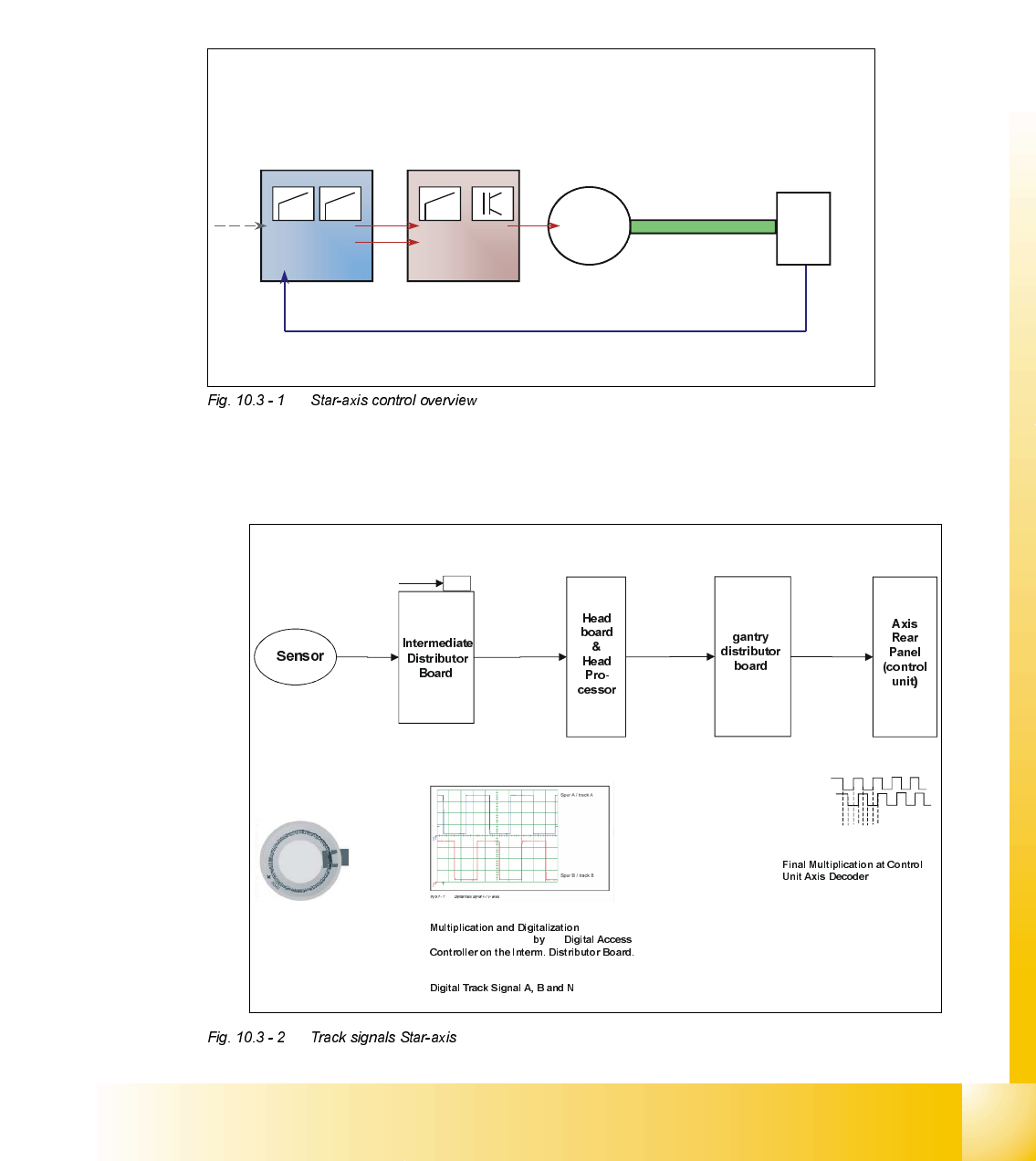
6WDUD[LVFRQWURORYHUYLHZ
%DVLFFRPSRQHQWVRIWKH6WDUD[LVGULYH
An axis controller, a servo amplifier and a motor generates all Star axis movements in the machine
controlled by the track signals.
7UDFNVLJQDOV
A axis controller,a servo amplifier and a axis drive generate all movements in the machine.
Digital axis
controller
Analog servo
amplifier
Axis drive 3 phase AC
digital position
detection with feed
back loop
SIPLACE HS50-machines have on each gantry three of this 3 phase AC - axes. (X-Y-Star)
M
3~
Track signals
Incremental
encoder
Track Signal - Star Axis (not adjustable)
X12as
(2) A
(5) B
(1) GND
(7) +5V
(8) N
X2as X13ac
(39) A
(38) A not
(36) B
(35) B not
(33) N
(32) N not
Rotor
Scale
(3600 ticks / 360° of scale)
A
B
(zero
pulse) sent to Interm. Distributor Board.
of the Analogue
Track Signals A, and B
the
(Multiplication by a factor of 10 for Digital Conversion)
12341234…..
X15
Connection for Track
Signal Test Box
Sensor
X4ac X4aa
(33) A
(32) A not
(30) B
(29) B not
(27) N
(26) N not
3.6 Vpp
X28aa X5tk
(2) A
(3) A not
(5) B
(6) B not
(8) N
(9) N not
.
(Multiplication by factor of 4)
End Result:
(3600) x (25) x (4) =
144,000 pulses / 360
°
Therefore ....
1 digit = 0.0025°
07/2002 Edition Student Guide HS-50 Advanced II
10 Star Axis
10
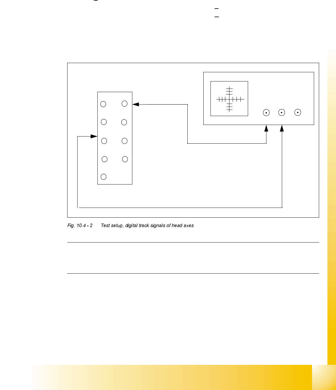
&KHFNLQJWKHWUDFNVLJQDOV
7HVWLQJ7RROV
– One 2-channel storage oscilloscope > 20 MHz, Test pins 1.4 mm, 1.5 mm and 1.6 mm
2YHUYLHZ
'LJLWDO7UDFN6LJQDOVRIWKH+HDG$[HV
0HDVXUHPHQWRIWKH7UDFN6LJQDOVRI6WDU=DQG'3$[HVDWWKH,QWHUPHGLDWH'LVWULEXWRU
63
$[HV $GMXVWPHQW 2VFLOORVFRSH'LVSOD\
star none pulse signal amplitude 3.6V
ss
z none pulse signal amplitude 3.6V
ss
dp read head on 1.5 mm,
parallel to glass pane
pulse signal amplitude 3.6V
ss
Student Guide HS-50 Advanced II 07/2002 Edition
10 Star Axis
11
; = z-axis
; = star - axis
; = dp - axis
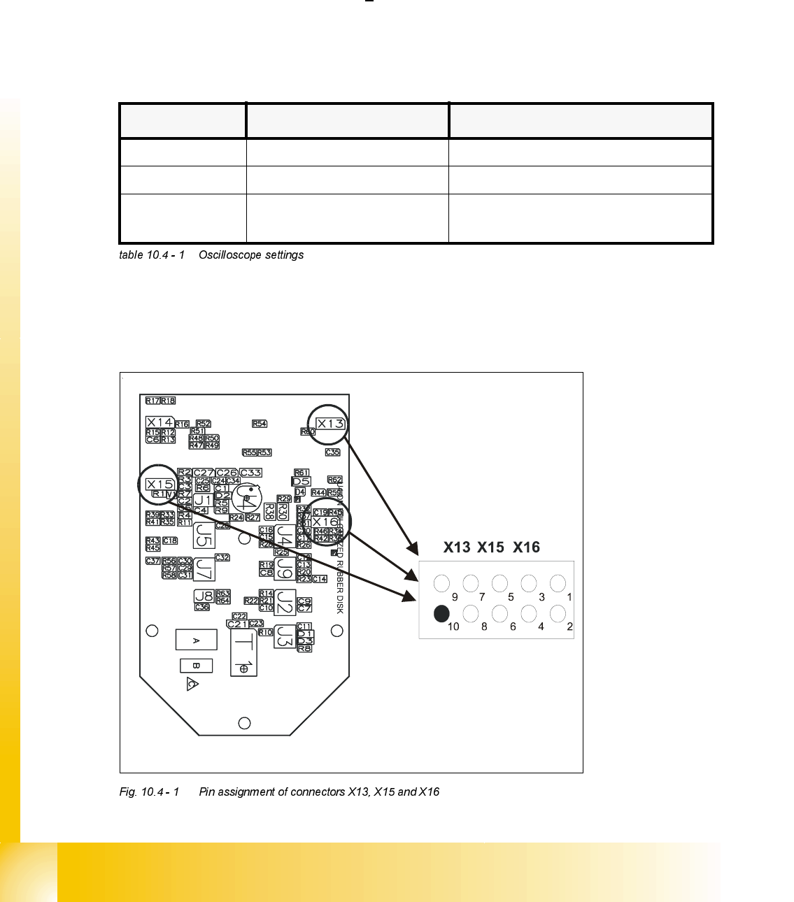
3LQDVVLJQPHQW
7HVW6HWXS
NOTE
At present, there is no measuring adapter available. Therefore, the track signals can only be
measured on the pins.
1. Ground 2. Track A
3. Track A
4. Ground
5. Track B 6. Track B
7. Track N 8. Track N
9. -4V 10.removed
12
3
4
5
6
78
9
10
X
CH1
CH2
EXT
X13 / X15 / X16