HS50_advance_level 2.pdf - 第387页
Stud ent Gu ide HS-5 0 Adva nced II 07/2 002 Ed ition 14 Conve yor System 13 /D\ RXWRI0HFKD QLFDODQG (OHFWULFD O$ VVHPEO LHV

07/2002 Edition Student Guide HS-50 Advanced II
14 Conveyor System
12
2YHUYLHZ
$EEUHYLDWLRQV8VHG
– PCB = Printed Circuit Board
– PCB1 / PCB2 = PCB transport section 1 / 2
– Sonar proximity switch = Ultrasonic sensor (Sensing head incl. amplifier)
– Proximity switch = Inductive proximity switch
&RQVWUXFWLRQDQG)XQFWLRQ
The PCB conveyor system may be designed as a single conveyor (only conveyor 1 is installed)
or as a dual conveyor (see ).
Each conveyor (1 / 2) consists of 5 components:
Input conveyor, conveyor placement area 1(4), intermediate conveyor, conveyor placement
area 2 (3) and output conveyor (see ).
The width of each PCB conveyor system (conveyor 1 and 2) can be adjusted continuously inde-
pendently of the other. The desired PCB conveyor width can be specified in the menu "Width adj.
system". Depending on the speed previously selected (slow / fast), the automatic width adjust-
ment system sets the conveyor width slowly or quickly to the desired width. The range of adjust-
ment for the conveyor width ranges from min. 50 mm and max. 460 mm.
Limit switches limit the possible travel ranges (minimum and maximum).
Triggering a limit switch (input signal turns to 1 briefly) resets the output for the motor of the con-
veyor width adjustment system, i.e., the motor - and thus the movement - is stopped.
Within the conveyor system the PCB is transported on the conveyor toothed belts which are
arranged in pairs and are driven by a d.c. geared motor.
Sonar proximity switches on each conveyor unit monitor the transport section at each conveyor
unit and thus monitor the presence of the PCB.
The stopper in placement areas 1 and 2 (3 and 4) can be extended pneumatically, stopping the
PCB in the exact X-position. The lifting table is then moved up. As a result, the holddown devices
on the fixed and the movable side of the conveyor are moved down, clamping the PCB in place.
Prior to placement the PCB vision system ascertains the exact position of the PCB clamped in
the PCB conveyor. The deviations in position which are ascertained are incorporated into the
placement coordinates.
Student Guide HS-50 Advanced II 07/2002 Edition
14 Conveyor System
13
/D\RXWRI0HFKDQLFDODQG(OHFWULFDO$VVHPEOLHV

07/2002 Edition Student Guide HS-50 Advanced II
14 Conveyor System
14
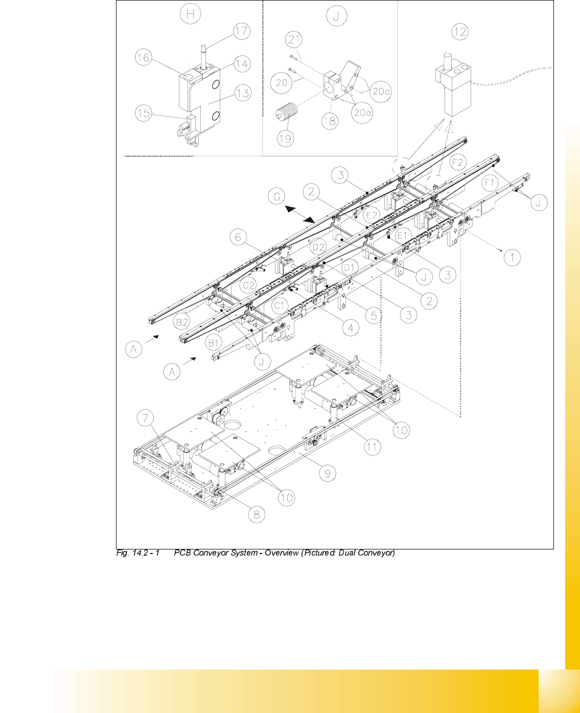
Key to
A) PCB transport direction B) Input (B1 / B2)
C) Placement area 1 or 2 (C1 / E1) D) Intermediate conveyor (D1 / D2)
E) Placement area 3 or 4 (C2 / E2) F) Output belt (F1 / F2)
G) Travelling direction of width adj. system H) Detail: PCB stopper
I) -------------- J) Detail: Sonar proximity switch mount sensing
head of proximity switch
1 Screws to fasten the conveyor assem-
blies to the slide unit of the conveyor
assemblies and the base unit
(two M5 hexagonal socket head cap
screws for each)
2 Fixed conveyor side, right-hand
(conveyor 1 / 2)
3 Movable conveyor side, left-hand (con-
veyor 1 / 2)
4 Rocking lever (2 levers per conveyor 1 / 2)
5 Stopper pin at top and bottom 6 PCB stopper (per placement area)
7 Conveyor mount 1
(2 each per movable side)
8 Conveyor mount 2
(2 for each fixed side)
9 Mounting plate for PCB handling unit 10 Lifting table plate (2 for each conveyor 1/2)
11 Guide pillars for lifting table plate 12 Proximity switch for the wide adjustment sys-
tem (per movable side)
13 PCB stopper, basic module 14 Cover with inductive proximity switch for
stopper position
15 Solenoid valve to move stopper in and
out
16 Sonar proximity switch for check on presence
of PCB
in placement areas 1 to 4
17 Piston rod 18 Mount for sonar proximity switch
19 Sonar proximity switch for check of PCB
present in input, intermediate and
output conveyor
20 Fasteners for sonar proximity switch mount
2 hexagonal socket head cap screws M3 x20,
using holes 20a or 20b, depending of con-
veyor area
21 Clamping unit for sonar proximity
switches (sensing head): 1 hexagonal
socket head cap screw M3 x 16
22 -----------