HS50_advance_level 2.pdf - 第424页
07/2002 Editio n Student G uide HS -50 Advanc ed II 14 Conveyor System 50 ([F KDQJLQJWK H3UR[LPLW\6ZLWFK IRU6 WRSSHU 3RVLWLRQ Fig. 14.3.1 1 Exchanging the Prox imity Switch or Solenoid Valve on the Stopper…

Student Guide HS-50 Advanced II 07/2002 Edition
14 Conveyor System
49
In case of a problem with the sonar proximity switch sensing head:
➠ Loosen the clamping unit of the sonar proximity switch sensing head and pull out the sensing
head.
➠ For the electrical isolation, proceed through the following steps>
➠ Lift off the cover of the cable duct in question.
➠ Carefully (!) remove the corresponding cable ties.
➠ Run the cable of the faulty sonar proximity switch sensing head carefully (!) so that it
weaves its way as far as the sonar proximity switch amplifier (layout: see ).
➠ Pull off the plug-and-socket connection of the sensing head at the allocated amplifier (see ).
In case of a problem with the sonar proximity switch amplifier:
➠ Pull the cable of the sensing head at the faulty amplifier and loosen the screw connection of
the cable on the bottom of the amplifier.
➠ Loosen the screws fastening the corresponding amplifier package (2 hexagonal socket head
cap screws M 5 x 70, see ).
-> The RUGHU of the amplifiers in the package must be maintained.
➠ Remove the faulty amplifier.
,QVWDOOLQJWKH6RQDU3UR[LPLW\6ZLWFK6HQVLQJ+HDG$PSOLILHU
➠ Where applicable, push the new sonar proximity switch VHQVLQJKHDG into the hole such that
the DVVHPEO\GLPHQVLRQmeasured is restored. Clamp the sensing head H[DFWO\in this po-
sition.
➠ Where applicable, insert the new sonar proximity switch DPSOLILHUV into the amplifier package
in the correct order and screw the package tight (see ).
Make the plug-and-socket and screw connection.
➠ Carry out all further assembly steps in the reverse order to that during removal.
➠ Remove all tools, etc., from the working area of the machine.
➠ Where applicable, fold down the transmission lever on the lifting table motor mount (see Fig.
14.3.5: illustration bottom left).
➠ Install the lifting table as described in section 14.3.9.2.
➠ Carry out the pertinent )LQDOVWHSVLQFOXGLQJIXQFWLRQFKHFN(see section 14.4). Use the
"Setting Instructions for HS-50" to calibrate the sonar proximity switch amplifier.
07/2002 Edition Student Guide HS-50 Advanced II
14 Conveyor System
50
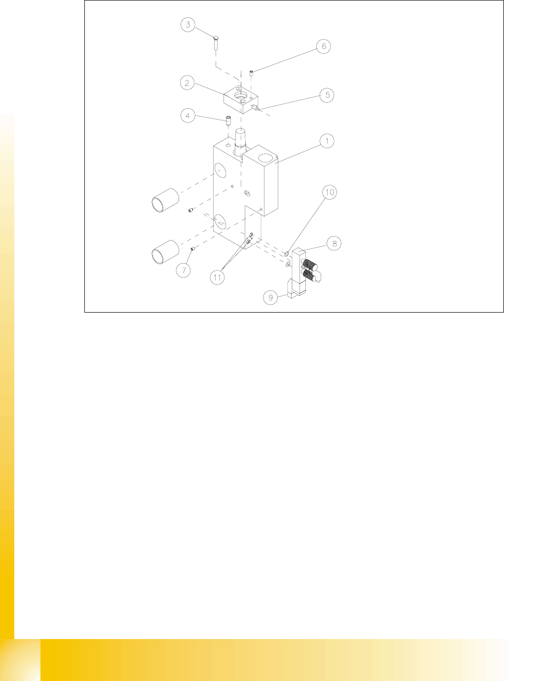
([FKDQJLQJWKH3UR[LPLW\6ZLWFKIRU6WRSSHU3RVLWLRQ
Fig. 14.3.11 Exchanging the Proximity Switch or Solenoid Valve on the Stopper
Key to Fig. 14.3.11
➠ Before removing the proximity switch, check the problem situation:
– If the control LED at the stopper does not light up in case of "Stopper moved out", the ac-
tuation distance is not set correctly or the supply voltage has been interrupted or the prox-
imity switch is faulty.
1) Basic stopper module 2) Cover: WILL NOT BE REMOVED
3) Slotted screw M 3 x 16 4) Spring-loaded pressure plate
5) Proximity switch for stopper position with
control LED
6) Clamping unit for proximity switch : set
screw M3
7) Clamping unit for sensing head of sonar
proximity switch: set screw M3
8) Valve assembly
9) Plug-and-socket connection of solenoid
valve
10) O-ring 3 x 1 NBR 70B
11) Screws to fasten the solenoid valve
2 hexagonal socket head cap screws
M1,6 x 14

Student Guide HS-50 Advanced II 07/2002 Edition
14 Conveyor System
51
– If the LED also lights up in case of "Stopper moved in", the proximity switch is faulty.
– If the LED lights up but there is not proximity switch signal (sequence comes to a halt with
an error message), there may be a break in the signal line in the proximity switch cable, a
poor plug-and-socket connection at SLIO module on PCB1 or PCB2 or a fault in the SLIO
assembly).
NOTE:
The proximity switches for the stopper position have cables with different lengths and therefore
have different Item Nos. .
For the exchange of this proximity switch the proximity switch cable must be run on a weaving
course as far as the SLIO module PCB1 or PCB2 (layout: see ). This may be somewhat compli-
cated due to the routing of the cable inside the machine base.
You may wish to contact the Siemens SMD Service regarding this work. 14
5HPRYLQJWKH3UR[LPLW\6ZLWFKIRUWKH6WRSSHU3RVLWLRQ
➠ Undo the clamping unit of the proximity switch on the mount and pull out the proximity switch.
➠ Take off the corresponding cable cut cover and FDUHIXOO\remove the cable ties.
➠ Check whether it would be helpful to pull in the new proximity switch cable with the aid of the
old cable, at least in a partial area.
➠ Proceed accordingly and FDUHIXOO\run the wiring of the proximity switch on a weaving
course as far as the SLIO module on PCB1 or PCB2 (layout: see ).
➠ Detach the plug-and-socket connection ; bzw. ;at the SLIO module PCB1 or PCB2 (see
circuit diagram 6/,2PRGXOHRQ3&% or 3&%).
,QVWDOOLQJWKH3UR[LPLW\6ZLWFKIRUWKH6WRSSHU3RVLWLRQ
➠ Initially, push the new proximity switch only YHU\VOLJKWO\ into the hole and do FODPS the prox-
imity switch LQWKLV position.
➠ Carry out all further assembly steps in the reverse order to that described for removal.
➠ Remove all tools, etc., from the working area of the machine.
➠ Load the SITEST program and activate the stopper. Push the proximity switch so far into the
hole that it switches reliably when the stopper (piston) is moved RXWit (change of signal 0 -> 1).
The control LED on the proximity switch must light up. &ODPS the proximity switch in this po-
sition.
([FKDQJLQJWKH6ROHQRLG9DOYH5HPRYDODQG,QVWDOODWLRQ
➠ Pull off the plug-and-socket connection on the faulty solenoid valve.
➠ Undo the screws fastening the solenoid valve to the stopper base unit (2 hexagonal socket
head cap screws M1,6 x 14).
➠ Install the new solenoid valve in the reverse order.