HS50_advance_level 2.pdf - 第168页
07/2002 Editio n Student G uide HS -50 Advanc ed II 7 X-Axis 10 (1) Trailing cabl e (2) X/Y dis tributor (3) Primar y part of the linea r drive (4) Head mo unt (5) Three-ph ase A C motor for the X- axis (6) T ooth ed b…
Student Guide HS-50 Advanced II 07/2002 Edition
7 X-Axis
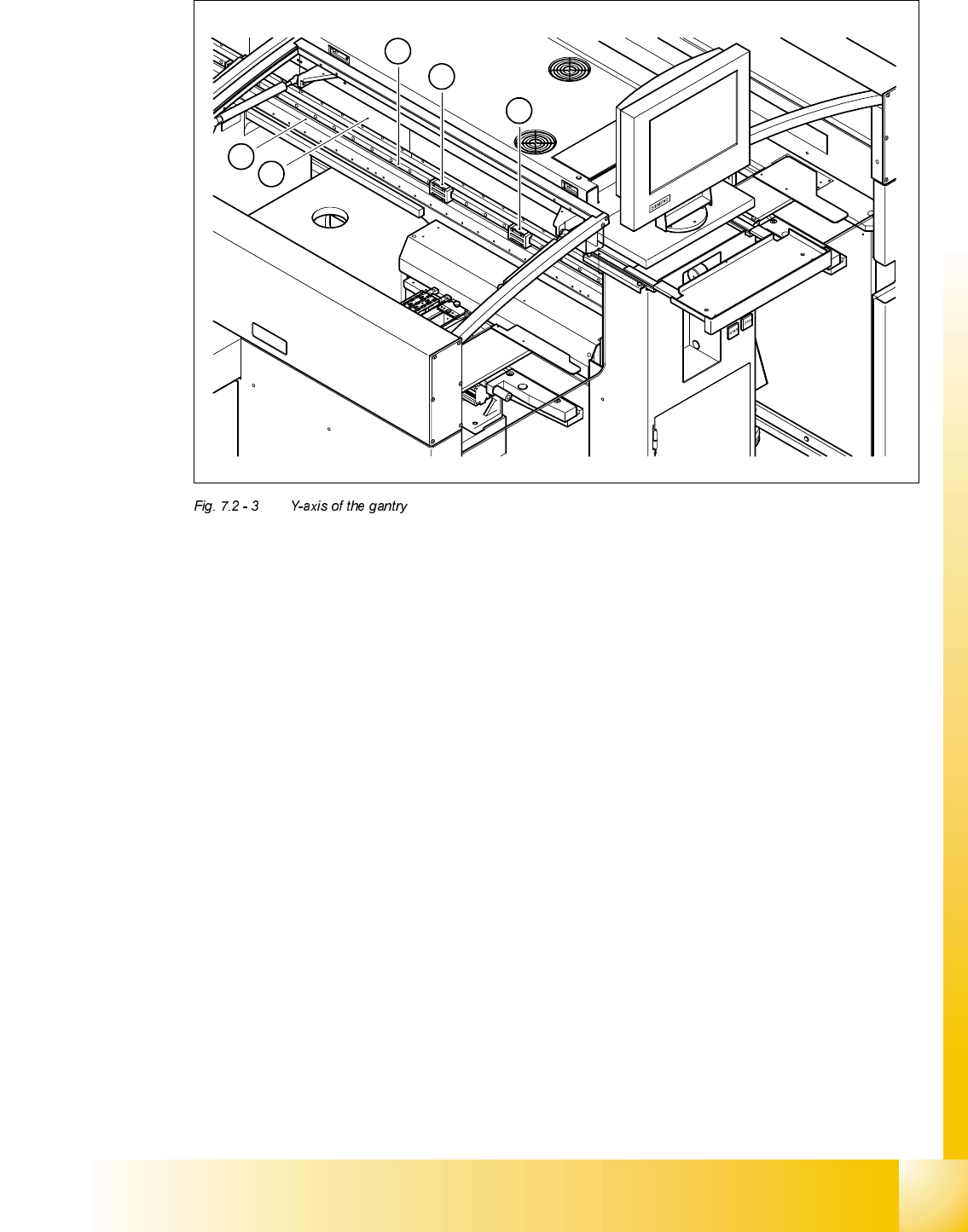
9
(1) Shuttles of the recirculating ball screw unit for the Y-axis
(2) Guide rail of the recirculating ball screw unit for the Y-axis
(3) Secondary part of the linear drive for the Y-axis (permanent magnets)
(4) Scale for the Y-axis
4
3
1
1
2
07/2002 Edition Student Guide HS-50 Advanced II
7 X-Axis
10
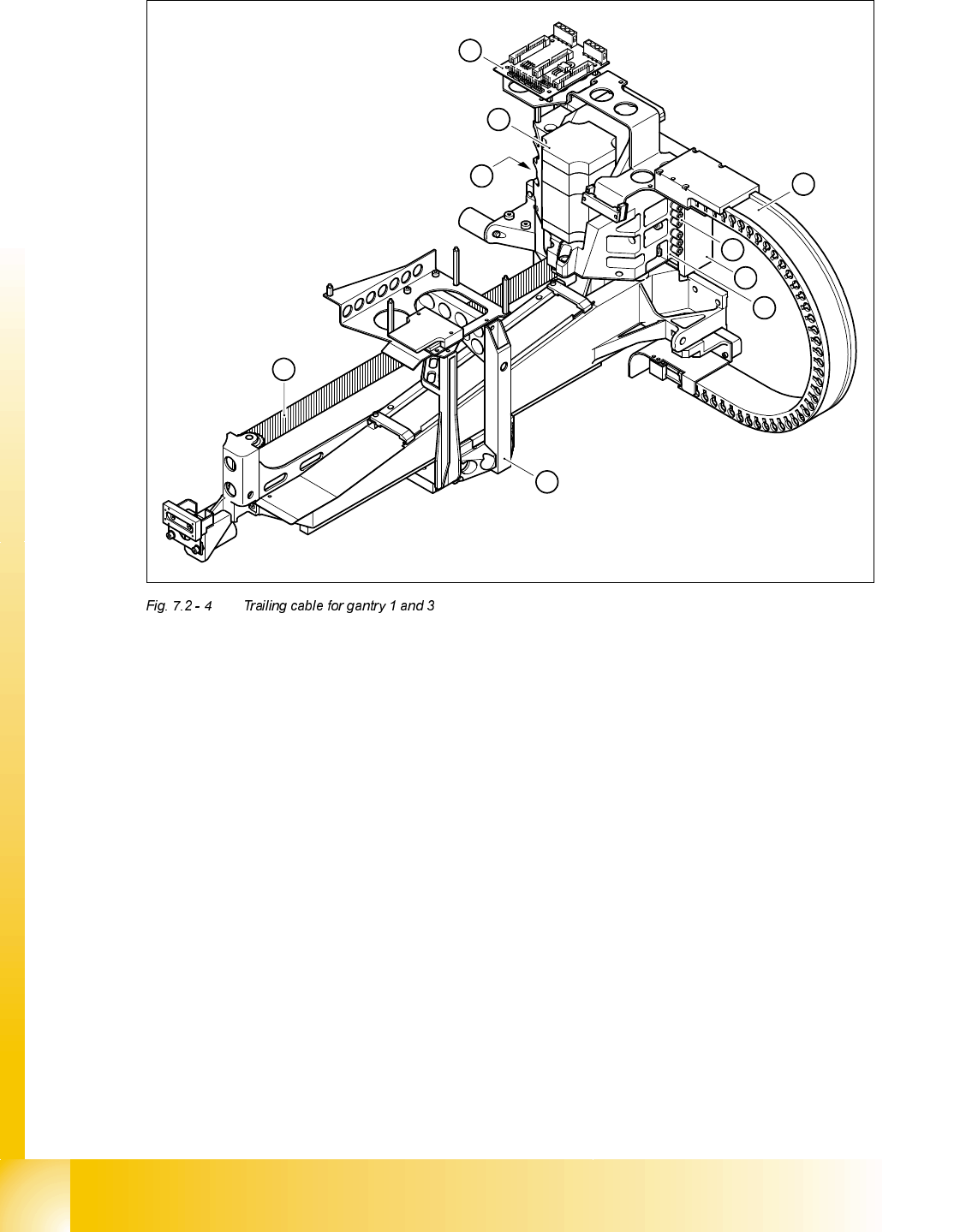
(1) Trailing cable
(2) X/Y distributor
(3) Primary part of the linear drive
(4) Head mount
(5) Three-phase AC motor for the X-axis
(6) Toothed belt for the X-axis
(7) Compressed air inlet couplings
(8) Compressed air outlet coupling
(9) Motor bracket
6
5
4
1
2
3
8
9
7

Student Guide HS-50 Advanced II 07/2002 Edition
7 X-Axis
11
(1) Gantry distributor
(2) Compressed air distributor
The other three ribbon cables supply power and transmit control signals for the gantry axis drives.
They connect the gantry distributor (see item 1 in Fig. 7.2 - 5
) to the X/Y distributor (item 2 in Fig.
7.2 - 4
).
The gantry is supplied with compressed air via seven compressed air hoses. The lines are con-
nected to the compressed air distributor (see item 2 in Fig. 7.2 - 5
). They run in the trailing cable
and end at the inlet couplings (see item 7 in Fig. 7.2 - 4
) on the motor bracket (see item 9 in Fig.
7.2 - 4
). Seven compressed air lines continue from the outlet couplings (see item 8 in Fig. 7.2 - 4)
to the collect&place head.
The X-axis motor (see item 5 in Fig. 7.2 - 4
) moves the head mount (see item 4 in Fig. 7.2 - 4) in
the x direction with the aid of a toothed belt (see item 6 in Fig. 7.2 - 4
). The mount is fixed to three
shuttles (see item 1 in Fig. 7.2 - 6
) on the two recirculating ball screw units (see item 2 in Fig.
7.2 - 6
) on the underside of the gantry. This layout guarantees that movement of the X-axis is both
precise and generates very little friction.
The head mount supports the collect&place head /DLM1 and the head board (see item 3 in Fig.
7.2 - 6
).
1
2