HS50_advance_level 2.pdf - 第54页
07/2002 Editio n Student G uide HS -50 Advanc ed II 3 Power Sup ply 16 PLEAS E NOTE: Remember to replac e the p erspex safety panel s over rectifi ers V1 and V7 when the measur e- ment s are com plet e. 5HFWLILH U ,Q…

Student Guide HS-50 Advanced II 07/2002 Edition
3 Power Supply
15
0HDVXULQJYROWDJHVDWUHFWLILHUV9WR9
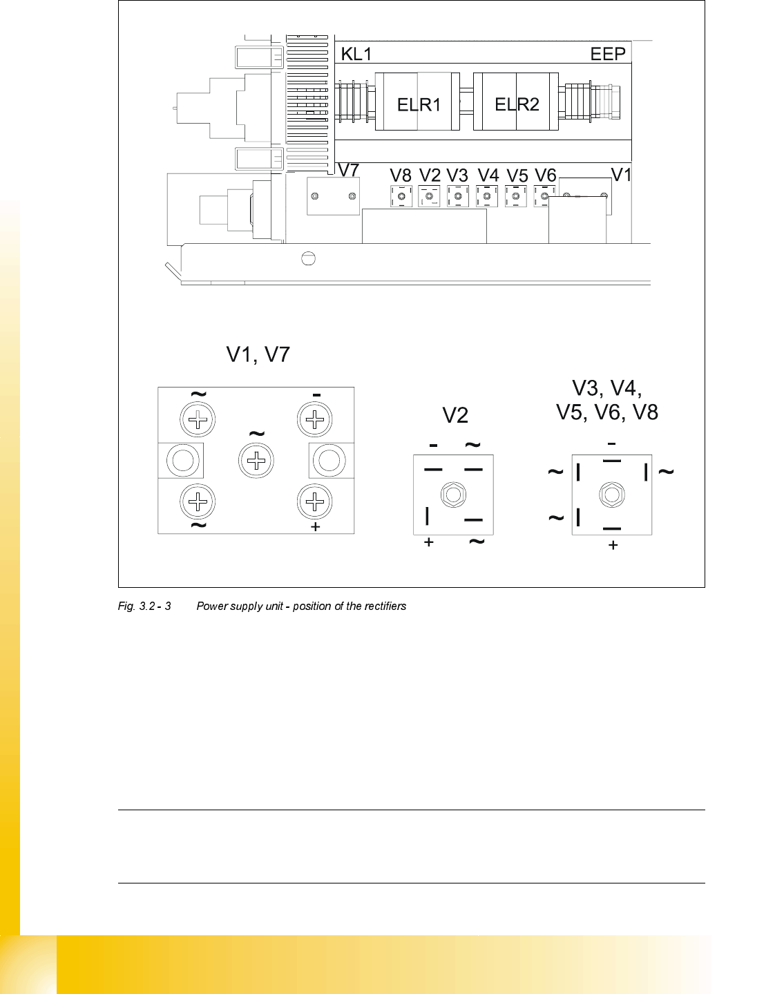
The following diagram shows the position of rectifiers V1 to V8 and their terminal assignments.
To take measurements on rectifiers V1 and V7, you must first remove the perspex safety panel.
RISK OF DEATH BY ELECTRIC SHOCK
➠ Switch the placement system off at the main switch.
➠ Disconnect the placement system from the power supply.
➠ Wait approximately 1 minute until the residual voltages have dropped to a safe level (electro-
lytic capacitor C1).
➠ Loosen the two M5 fillister head screws on rectifiers V1 and V7.
➠ Remove the perspex safety panel.
➠ Switch the placement system on and start it up.
➠ Measure the voltages.
PLEASE NOTE:
The placement system must have started, otherwise there will be no AC voltage (3 x 140 VAC) at
rectifier V1. V1 uses the 3 x 140 VAC to generate the 200 VDC supply voltage for the servo am-
plifiers of the gantry axes and 100 VDC for the servo amplifiers of the star axes. These 100 VDC
and 4 VDC supplies are fed to the AC voltage inputs of rectifier V2. Rectifier V2 serves to "OR"
the 4 VDC and 100 VDC supplies. If the placement system has not started, only 4 VDC will be
present at the positive pole of rectifier V2.
07/2002 Edition Student Guide HS-50 Advanced II
3 Power Supply
16
PLEASE NOTE:
Remember to replace the perspex safety panels over rectifiers V1 and V7 when the measure-
ments are complete.
5HFWLILHU ,QSXW 2XWSXW
V1 3 x 140 VAC 200 VDC
V2 100 VDC 100 VDC
V3 3 x 5 VAC 4 VDC
V4 3 x 24 VAC 30 VDC
V5 3 x 25 VAC 40 VDC
V6 3 x 6 VAC 10 VDC
V7 3 x 38 VAC 52 VDC
V8 3 x 20 VAC 30 VDC
Student Guide HS-50 Advanced II 07/2002 Edition
3 Power Supply
17
RISK OF DEATH BY ELECTRIC SHOCK
➠ Switch the placement system off at the main switch.
➠ Disconnect the placement system from the power supply.
➠ Wait approximately 1 minute until the residual voltages have dropped to a safe level (electro-
lytic capacitor C1).
➠ Attach the perspex safety panel and fix in place with the M5 fillister head screws.
CAUTION
Do not overtighten the fillister head screws. The perspex panel might break.
0HDVXULQJYROWDJHVDWWUDQVIRUPHU7
3ULPDU\VLGHRIWUDQVIRUPHU7
The transformer can be connected to the following main power supplies:
3 x 230 VAC for the "on-board electrical system" is drawn at terminals 1U5, 1V5 and 1W5. This is
used to supply the PC, the monitor and the lifting table motors.
Voltage Terminals
3 x 204 VAC (U. S. A.) ± 5 %, 50/60 Hz 1U6, 1V6, 1W6
3 x 230 VAC ± 5 %, 50/60 Hz 1U5, 1V5, 1W5
3 x 380 VAC ± 5 %, 50/60 Hz 1U4, 1V4, 1W4
3 x 400 VAC (Europe) ± 5 %, 50/60 Hz 1U3, 1V3, 1W3
3 x 415 VAC ± 5 %, 50/60 Hz 1U1, 1V1, 1W1